Supercharge Your Innovation With Domain-Expert AI Agents!

Piston and machining technology thereof

A processing technology and piston technology, applied in the field of compressor processing, can solve the problems of processing deformation, no improvement in mechanical efficiency, loss of mechanical efficiency, etc., and achieve the effect of strengthening lubrication, reducing friction area and reducing transmission error.

Inactive Publication Date: 2018-11-02
CHANGHONG HUAYI COMPRESSOR CO LTD
View PDF10 Cites 0 Cited by
  • Summary
  • Abstract
  • Description
  • Claims
  • Application Information

AI Technical Summary

Problems solved by technology

However, the mechanical efficiency of this structure is not improved in practical application, the dispersion is poor, and even the individual efficiency decreases.
The main reason is that the processing technology is to fine-grind the outer cylindrical working surface 1 of the piston first and then use a special milling machine (because it is finished and then milled, the special milling machine equipment is very expensive, and a single imported equipment costs more than 1 million yuan. According to The beat needs 4 such devices, that is, more than RMB 4 million) to mill the skirt groove 2, because the milling skirt groove 2 is after finishing, during the clamping and processing process, on the piston outer cylindrical working surface 1, " Pinch, pinch, processing deformation, etc.", which makes the processing quality of the piston (even obvious bump, pinch, pinch phenomenon visible to the naked eye) and precision (cylindricity, roundness, roughness, etc. significantly decreased) drop significantly, The effect is not reflected, and even the loss of mechanical efficiency occurs in some cases
The reason why the skirt groove 2 is milled after fine grinding is because if the skirt groove 2 is milled first, and then the outer cylindrical working surface 1 of the piston is finely ground, the roundness and cylindricity of the outer cylindrical working surface 1 of the piston cannot be guaranteed , because after the skirt groove 2 is milled, the corresponding part of the piston outer cylindrical working surface 1 is not a complete circle, and its roundness cannot be guaranteed if it is finely ground
[0003] Therefore, after the traditional structure has been applied for a period of time, it has basically stopped being used because it did not achieve the expected effect.

Method used


Image

  • Piston and machining technology thereof
  • Piston and machining technology thereof

Examples


Embodiment Construction

[0017] Preferred embodiments of the present invention will be described in detail below in conjunction with the accompanying drawings.

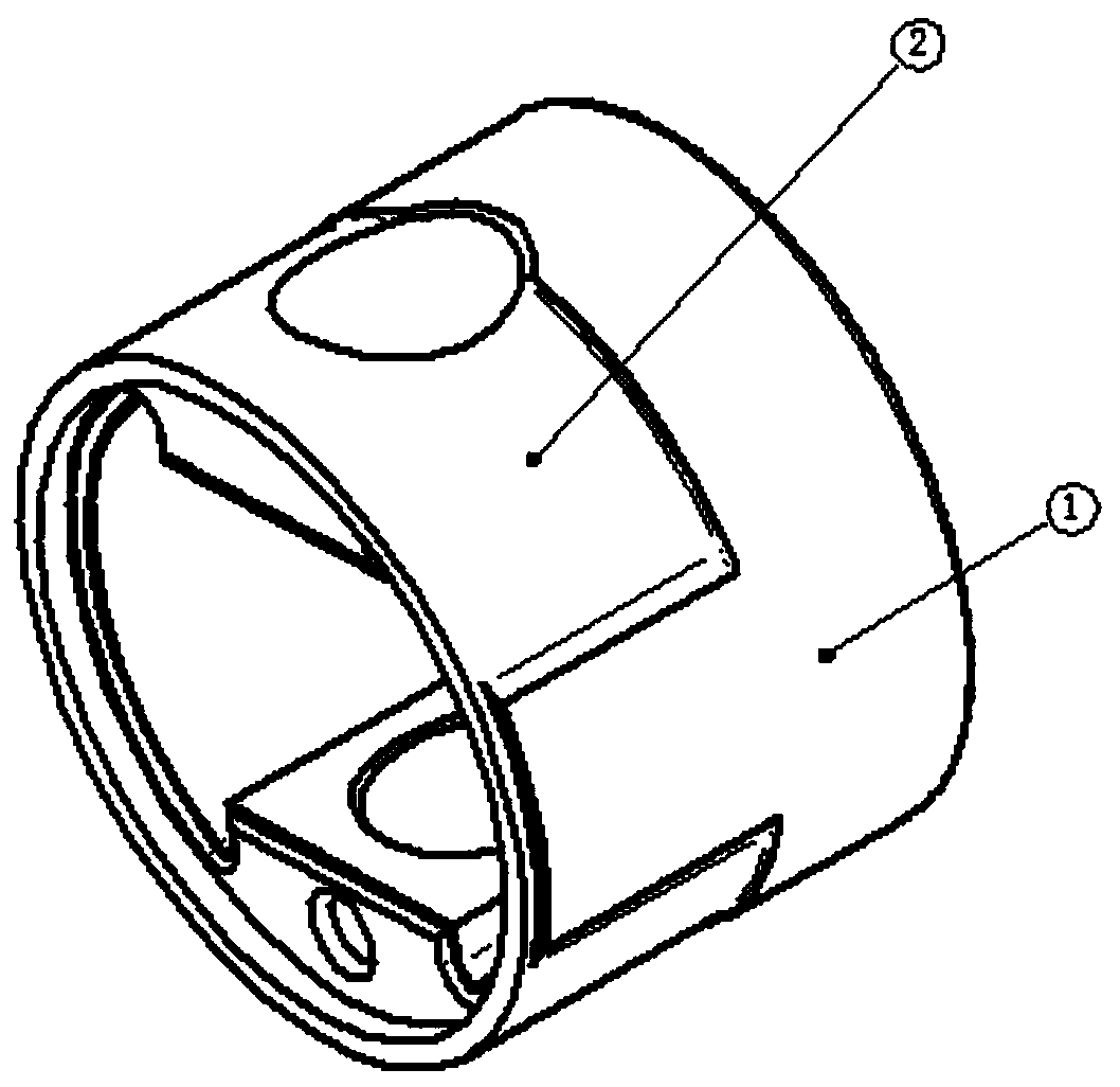
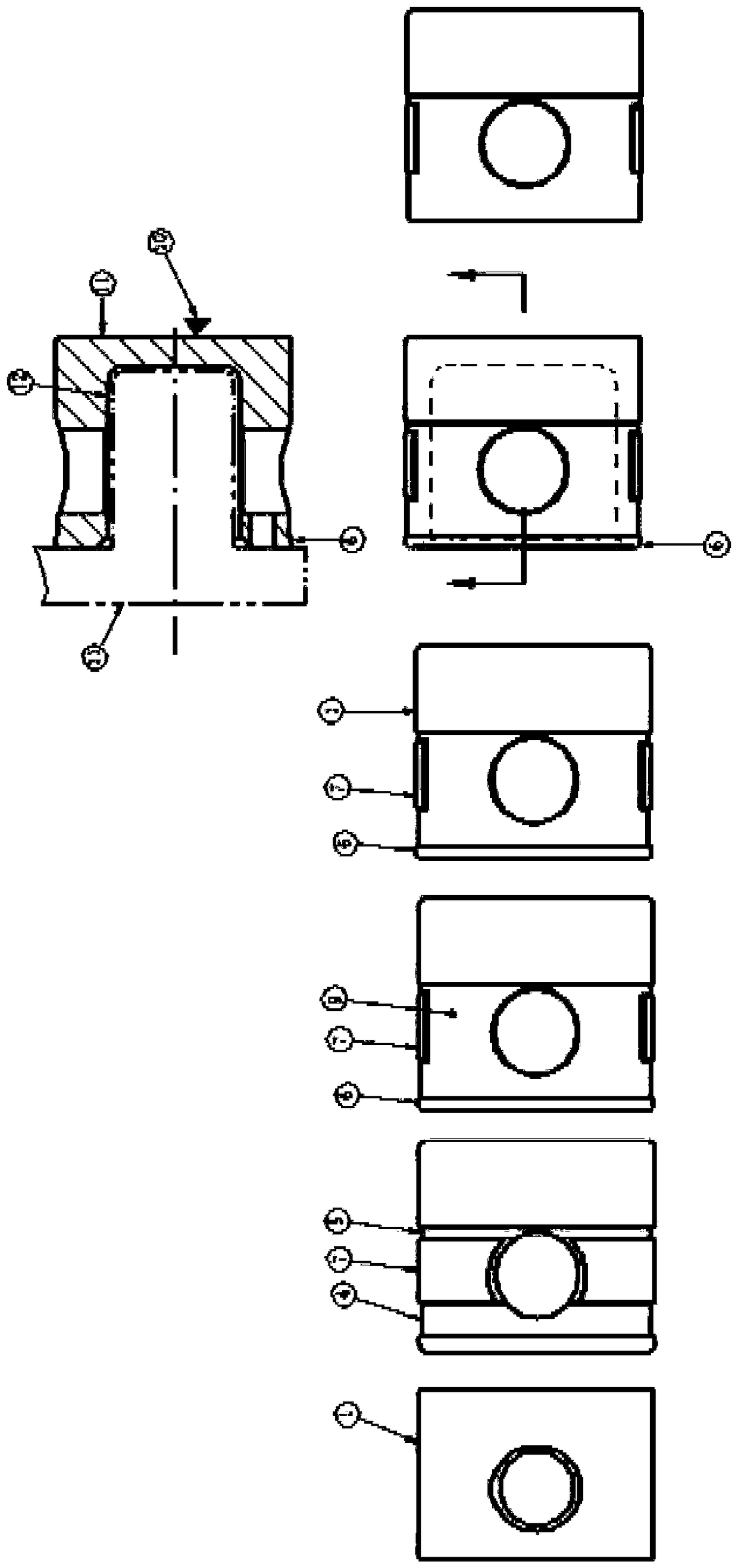
[0018] figure 1 with figure 2 Show the specific embodiment of the present invention: the first step rough grinding piston outer cylinder working surface 1, the second step car oil groove 5 and process groove 4, the third step milling through piston outer cylindrical surface 7, the fourth step fine grinding piston outer cylinder Working surface 1, piston outer cylindrical surface 7, piston outer cylindrical surface 6 (because at the two ends of the piston, there are piston outer cylindrical working surface 1 and piston outer cylindrical surface 6, and they are complete circles, so they can be finely ground directly, and can Ensure good machining accuracy), the fifth step is to car the outer cylindrical surface 6 of the piston (the width of the outer cylindrical surface 6 of the piston is very narrow 0.5-1mm, the machining allowance is very s...


PUM


Abstract

The invention discloses a machining technology of a piston. The technology comprises the following steps that 1) roughly grinding is carried out on an piston outer cylindrical working surface ; 2) anoil groove and a technology groove are lathed in the piston outer cylindrical working surface; 3) milling is carried out on a piston outer cylindrical face thoroughly; 4) finely grinding is carried out on the piston outer cylindrical working surface, the piston outer cylindrical face and the piston outer cylindrical face; and 5 ) the outer cylindrical face is lathed, positioning is carried out according to the inner cavity non-working face of the piston, the inner cavity non-working face of the piston is positioned through a positioning tool, and tight clamping points are arranged on the non-working face of the piston. According to the technology, the structure is mainly designed in cooperation with the machining technology of the invention, the structure is further improved at the same time, compared with a traditional structure, an oil tank 5 is additionally arranged, the oil tank 5 can be used for enhancing lubrication, the heat dissipation of the working face can be further accelerated, and thermal deformation can be reduced; and compared with the traditional structure, a technology groove 4 is additionally formed, so that the friction area is effectively reduced, and the efficiency is further improved.

Description

technical field [0001] The invention relates to the field of compressor processing, in particular. Background technique [0002] For the refrigeration compressors of fully enclosed refrigerators, it is hoped to improve the energy efficiency. The mechanical efficiency has reached more than 90% at present, and it is very difficult to further improve it. The traditional skirt piston design is as follows: figure 1 As shown, the outer cylindrical working surface 1 of the piston is a reciprocating friction surface. In order to reduce the transmission error, reduce the friction area, and improve the mechanical efficiency, after the piston is finely ground, a milling machine is used to mill out a skirt groove 2. However, in practical application of this structure, the mechanical efficiency is not improved, the dispersion is poor, and even the individual efficiency decreases. The main reason is that the processing technology is to fine-grind the outer cylindrical working surface 1 o...

Claims


Application Information

Patent Timeline
Patent Type & Authority Applications(China)
IPC IPC(8): B23P15/10
Inventor 盛正堂黄冬平饶超江亚光张龙飞刘济凯陈曦金文辉乐世鹏毛明烈
Owner CHANGHONG HUAYI COMPRESSOR CO LTD
Features
  • R&D
  • Intellectual Property
  • Life Sciences
  • Materials
  • Tech Scout
  • Unparalleled Data Quality
  • Higher Quality Content
  • 60% Fewer Hallucinations
Learn More