Automatic bonding device

A bonding device and a technology of a pressing device, applied in the direction of surface coating liquid devices, metal processing, metal processing equipment, etc., can solve the problem of low degree of operation automation, achieve automation and high work efficiency, and realize automatic The effect of bonding

Pending Publication Date: 2018-11-02
BESITER CO LTD
View PDF0 Cites 0 Cited by
  • Summary
  • Abstract
  • Description
  • Claims
  • Application Information

AI Technical Summary

Problems solved by technology

[0004] The purpose of the present invention is to provide an automatic bonding device, aiming at solving the problem of automation of the pressing operation of the entire welded part and the operation of fixing the entire welded part to the shell after the welding of the battery core and the circuit board assembly in the prior art is completed. less technical issues

Method used


Image

  • Automatic bonding device
  • Automatic bonding device
  • Automatic bonding device

Examples


Embodiment Construction

[0057] Embodiments of the present invention are described in detail below, examples of which are shown in the drawings, wherein the same or similar reference numerals designate the same or similar elements or elements having the same or similar functions throughout. The embodiments described below by referring to the figures are exemplary and are intended to explain the present invention and should not be construed as limiting the present invention.

[0058] In addition, the terms "first" and "second" are used for descriptive purposes only, and cannot be interpreted as indicating or implying relative importance or implicitly specifying the quantity of indicated technical features. Thus, a feature defined as "first" and "second" may explicitly or implicitly include one or more of these features.

[0059] It is to be understood that the terms "length", "width", "top", "bottom", "front", "rear", "left", "right", "vertical", "horizontal", "top" , "bottom", "inner", "outer" and ot...


PUM


Abstract

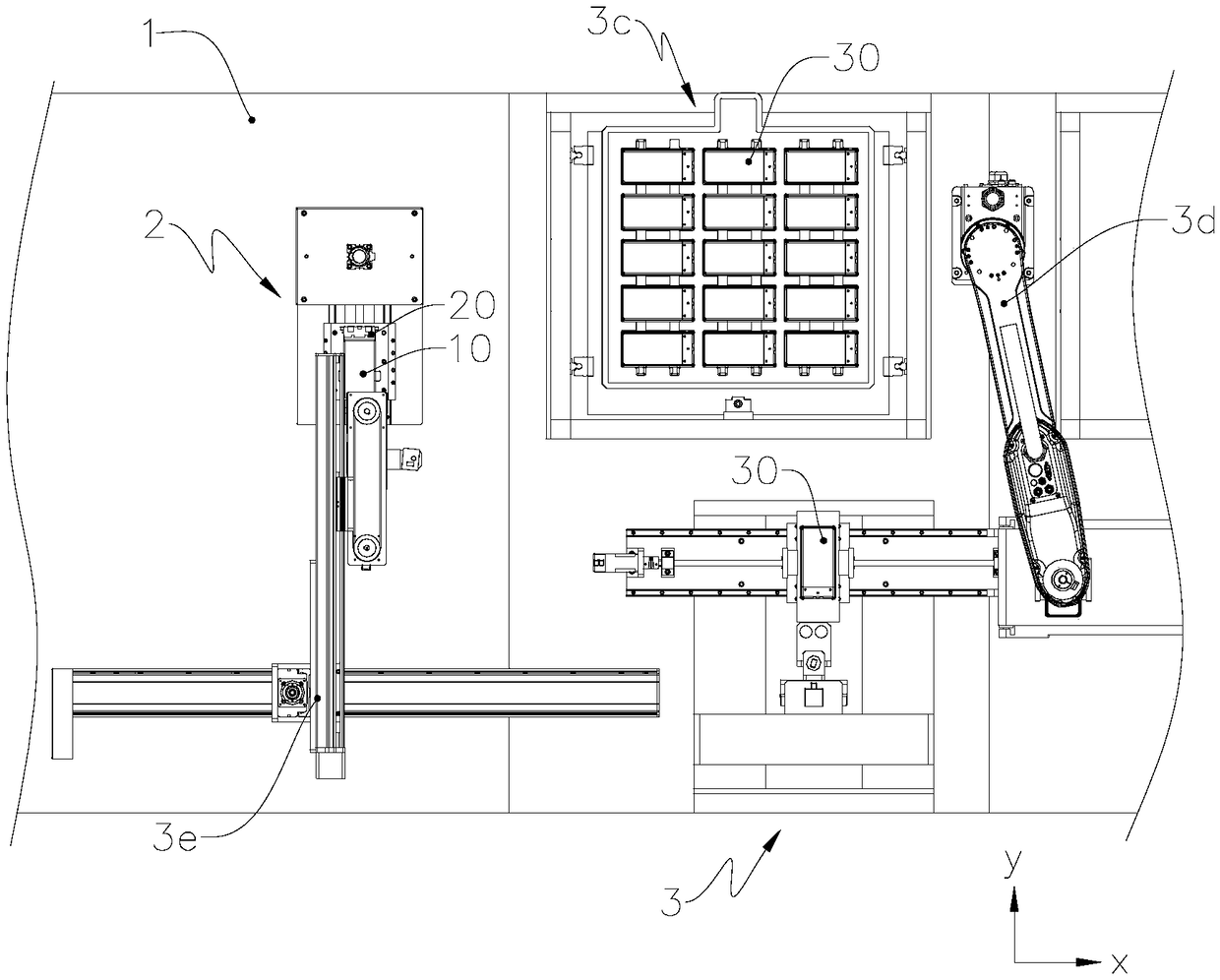
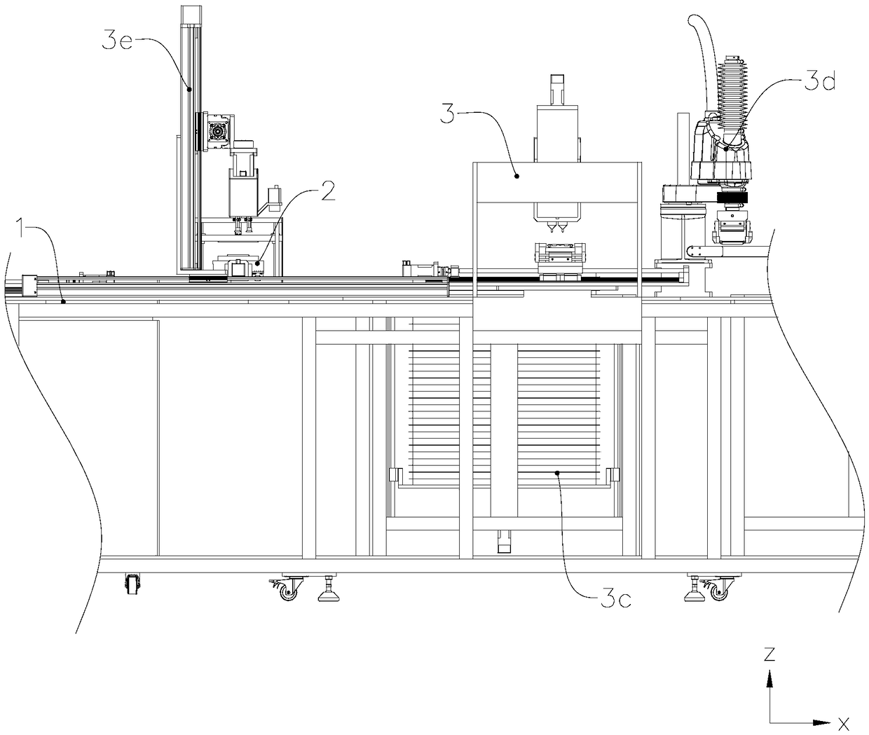
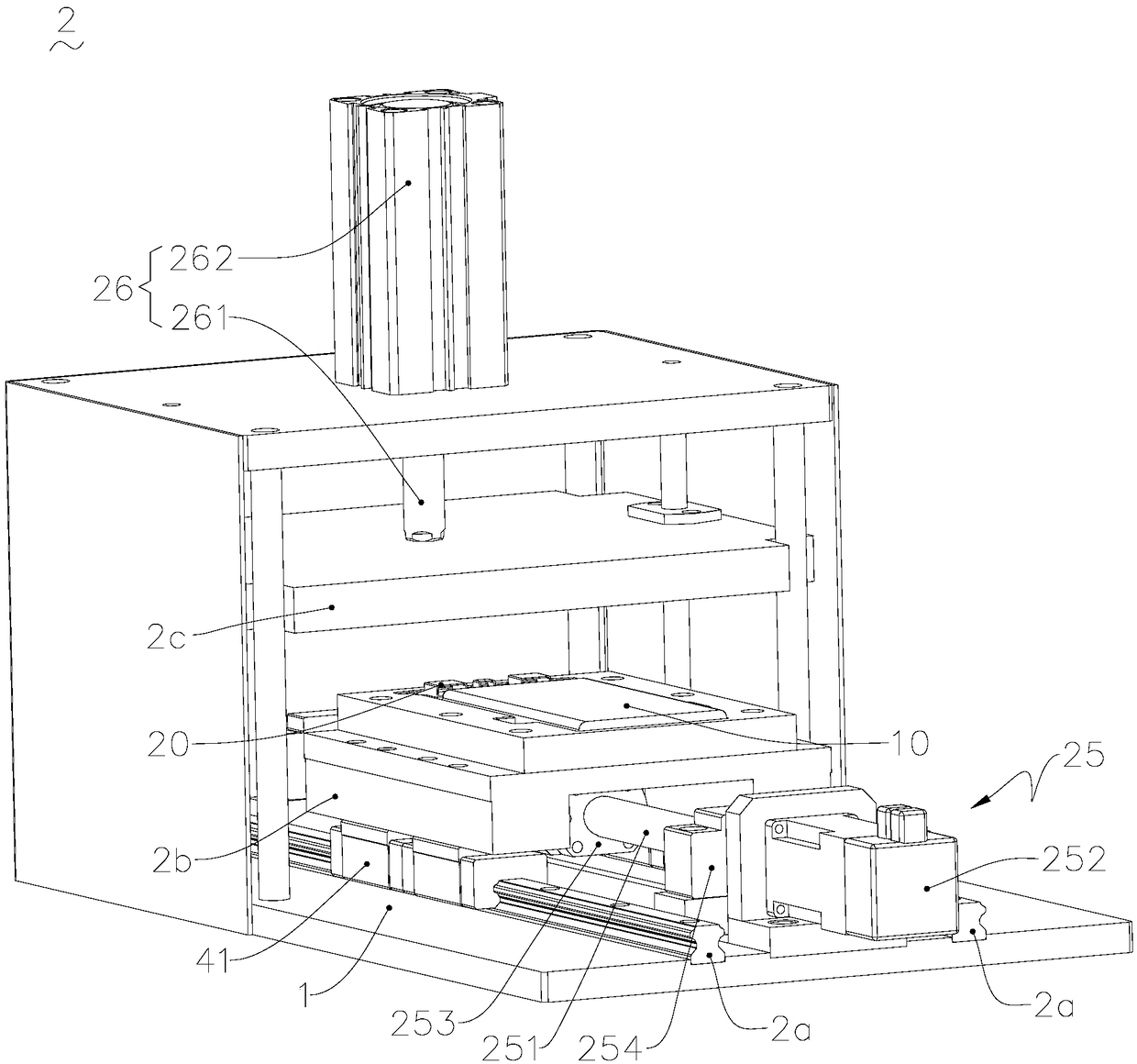
The invention relates to the field of movable power supply production equipment and provides an automatic bonding device. The automatic bonding device comprises a base, an automatic laminating device,an automatic adhesive dispensing machine and a welding part mechanical arm; the automatic laminating device, the automatic adhesive dispensing machine and the welding part mechanical arm are arrangedon the base; the automatic laminating device is used for laminating an electricity core assembly, namely an electricity core and a circuit board assembly which are mutually welded; the automatic adhesive dispensing machine is used for bonding the electricity core assembly after being laminated by the automatic laminating device on a housing; and the welding part mechanical arm is used for transferring the electricity core assembly on the automatic laminating device into the housing born by a housing sliding device. With the adoption of the structure, the automatic laminating device, the automatic adhesive dispensing machine and the welding part mechanical arm are integrated so as to achieve automatic laminating of the electricity core and the circuit board assembly, and automatic adhesivedispensing of the housing, so that a welding part meets the requirement of smoothness, automatic bonding between the electricity core assembly and the housing is also achieved, manpower is not required in the operating process, the automation degree is high, and the working efficiency is high.

Description

technical field [0001] The invention relates to the field of mobile power supply production equipment, in particular to an automatic bonding device. Background technique [0002] With the development of science and technology, the types of electronic products continue to increase. Due to the limited power of the batteries of electronic products, mobile power is usually required to charge electronic products to meet the short-term needs of people traveling and business trips; mobile power processing process Usually, the rechargeable battery (battery cell) and PCB (Printed Circuit Board, printed circuit board) are first assembled into one body. Since the battery cell is afraid of being squeezed, easily deformed, and easily punctured, the battery cell and PCB must be assembled. In a casing with a certain mechanical strength. [0003] In the traditional mobile power combination mounting process, the battery core and PCB are usually firstly pressed together by simple tools after...

Claims


Application Information

Patent Timeline
Patent Type & Authority Applications(China)
IPC IPC(8): B23P19/027B05C5/02
CPCB23P19/027B05C5/027
Inventor 潘良春
Owner BESITER CO LTD
Why Eureka
Try Eureka