
Floating grinding device and method of steel jacket for side rolling resistant torsion bar device

A technology of anti-rolling torsion bar and steel sleeve, which is applied in the direction of grinding drive device, grinding machine tool parts, grinding/polishing equipment, etc. Small margin, damaged torsion arm and other problems, to achieve the effect of repairing the wavy floating of the outer diameter size, limited grinding contact force, and high grinding accuracy

Active Publication Date: 2018-11-02
ZHUZHOU TIMES NEW MATERIALS TECH
View PDF7 Cites 3 Cited by
  • Summary
  • Abstract
  • Description
  • Claims
  • Application Information

AI Technical Summary

Problems solved by technology

[0004] After the torsion bar shaft is used, the installation end of the steel sleeve may have been deflected. After the steel sleeve is hot-fitted, the surface of the steel sleeve has a wavy deformation. The cylindrical grinder is rigid grinding. Although it can repair the wavy fluctuation of the outer diameter of the steel sleeve, it cannot correct the deflection of the steel sleeve. It is necessary to increase the machining allowance of the outer diameter of the steel sleeve.
Therefore, it is difficult to grind with an external cylindrical grinder
Furthermore, due to the small grinding allowance and high dimensional accuracy of the outer diameter of the steel sleeve, if manual sandpaper floating grinding is used, it can follow the deflection of the steel sleeve, but it cannot correct the wavy floating of the outer diameter of the steel sleeve. The cutting efficiency is low, the labor intensity of the workers is high, and the size control is prone to deviation

Method used


Image

  • Floating grinding device and method of steel jacket for side rolling resistant torsion bar device
  • Floating grinding device and method of steel jacket for side rolling resistant torsion bar device
  • Floating grinding device and method of steel jacket for side rolling resistant torsion bar device

Examples


Embodiment Construction

[0035] The following will be attached Figure 1~4 The present invention is further described with examples.

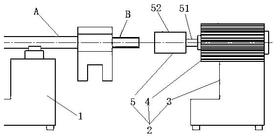
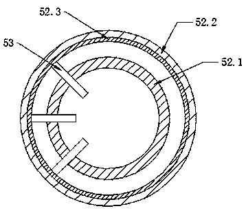
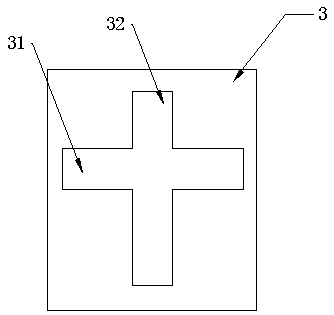
[0036] The steel sleeve floating grinding device for the anti-roll torsion bar device includes a support 1 horizontally supporting the torsion bar shaft A and a floating grinding assembly 2 for grinding the steel sleeve B on the torsion bar shaft A, and is characterized in that The floating grinding assembly 2 includes a motor base 3, a driving motor 4 mounted on the motor base 3 and capable of moving horizontally on the motor base 3, a circumferential grinding tool 5 coaxially installed on the rotating shaft of the driving motor 4, The central axis of the circumferential grinding tool 5 is at the same height as the central axis of the torsion bar shaft A, and the mobile drive motor 4 drives the circumferential grinding tool 5 to be set outside the steel sleeve B and coaxially aligned with the torsion bar shaft A. The grinding tool 5 is in elastic contact with the out...


PUM

PropertyMeasurementUnit
diameteraaaaaaaaaa

Abstract

The invention provides a floating grinding device and method of a steel jack for a side rolling resistant torsion bar device. The floating grinding device comprises a support for supporting a torsionbar shaft to horizontally arrange, and a floating grinding assembly for grinding the steel jack on the torsion bar shaft. The floating grinding device is characterized in that the floating grinding assembly comprises a motor base, a driving motor which is mounted on the motor seat and can horizontally move on the motor seat, and a circumferential grinding cutter which is coaxially mounted on a rotating shaft of the driving motor, wherein a central axis of the circumferential grinding cutter is as high as a central axis of the torsion bar shaft; the driving motor moves to drive the circumferential grinding cutter to sleeve the sleeve jack to be coaxially aligned with the torsion bar shaft; and the circumferential grinding cutter is in radial elastic contact with the outer circumferential surface of the steel jack. According to the floating grinding device, the wave-shaped fluctuation of the outside diameter of the steel jacket can be effectively recovered, and the deviated steel jacketcan be aligned on the basis that a torsion bar of the side rolling resistant torsion bar device is not damaged; in addition, the grinding efficiency is high; the processing reliability is high; and the operation is simple and convenient.

Description

technical field [0001] The invention relates to a steel sleeve floating grinding device and method for an anti-rolling torsion bar device, belonging to the technical field of anti-rolling torsion bar devices for rail vehicles. Background technique [0002] The anti-roll torsion bar device usually includes three parts: the torsion bar assembly, the connecting rod assembly and the support seat assembly. In the torsion bar assembly, the torsion bar shaft generates a reaction force through torsion when the vehicle body rolls, and it is fed back to the vehicle through the connecting rod assembly. body, providing roll stiffness. [0003] When the torsion bar device rolls around the X-axis, the steel sleeve rotates in the rotary pair of the support seat. During the movement, the steel sleeve and the graphite lining in the support seat rub against each other, and the size of the steel sleeve will be affected due to wear. And reduce. After a period of time (generally 3 years) has p...

Claims


Application Information

Patent Timeline
Patent Type & Authority Applications(China)
IPC IPC(8): B24B5/04B24B47/20B24B1/00
CPCB24B1/00B24B5/04B24B47/20
Inventor 张山太晏红卫吴坚王小臣杜方孟王卫平
Owner ZHUZHOU TIMES NEW MATERIALS TECH
Learn More