
Glass chamfering device convenient to adjust

A chamfering device, glass technology, applied in grinding/polishing safety devices, machine tools suitable for grinding the edge of workpieces, and parts of grinding machine tools, etc., can solve the problem of increasing chamfering time, difficulty in size, and affecting efficiency, etc. problems, to achieve the effect of enhancing stability, improving the quality of chamfering processing, and improving the convenience of operation

Inactive Publication Date: 2018-11-02
福建省三林生态科技有限公司
View PDF0 Cites 3 Cited by
  • Summary
  • Abstract
  • Description
  • Claims
  • Application Information

AI Technical Summary

Problems solved by technology

[0002] Glass chamfering machine is one of the commonly used equipment for glass production. After the glass is produced, it needs to be chamfered according to the requirements. The quick and convenient use of glass chamfering equipment will directly affect the production speed of glass. The design of glass chamfering equipment is not good. Reasonable, inconvenient to use, it will increase the chamfering time and affect the efficiency
[0003] In the current glass chamfering processing technology, the traditional manual chamfering method is generally used, but the manual chamfering method usually has imprecise chamfering, difficult to control the size, and the chamfering effect is often uneven due to the technical level of the processor. At the same time, some automatic chamfering technologies have also appeared, but these devices have the problems of complicated operation and inconvenient adjustment

Method used


Image

  • Glass chamfering device convenient to adjust
  • Glass chamfering device convenient to adjust
  • Glass chamfering device convenient to adjust

Examples


Embodiment Construction

[0021] The following will clearly and completely describe the technical solutions in the embodiments of the present invention with reference to the accompanying drawings in the embodiments of the present invention. Obviously, the described embodiments are only some, not all, embodiments of the present invention.

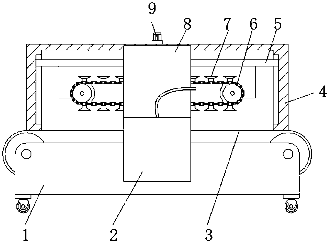
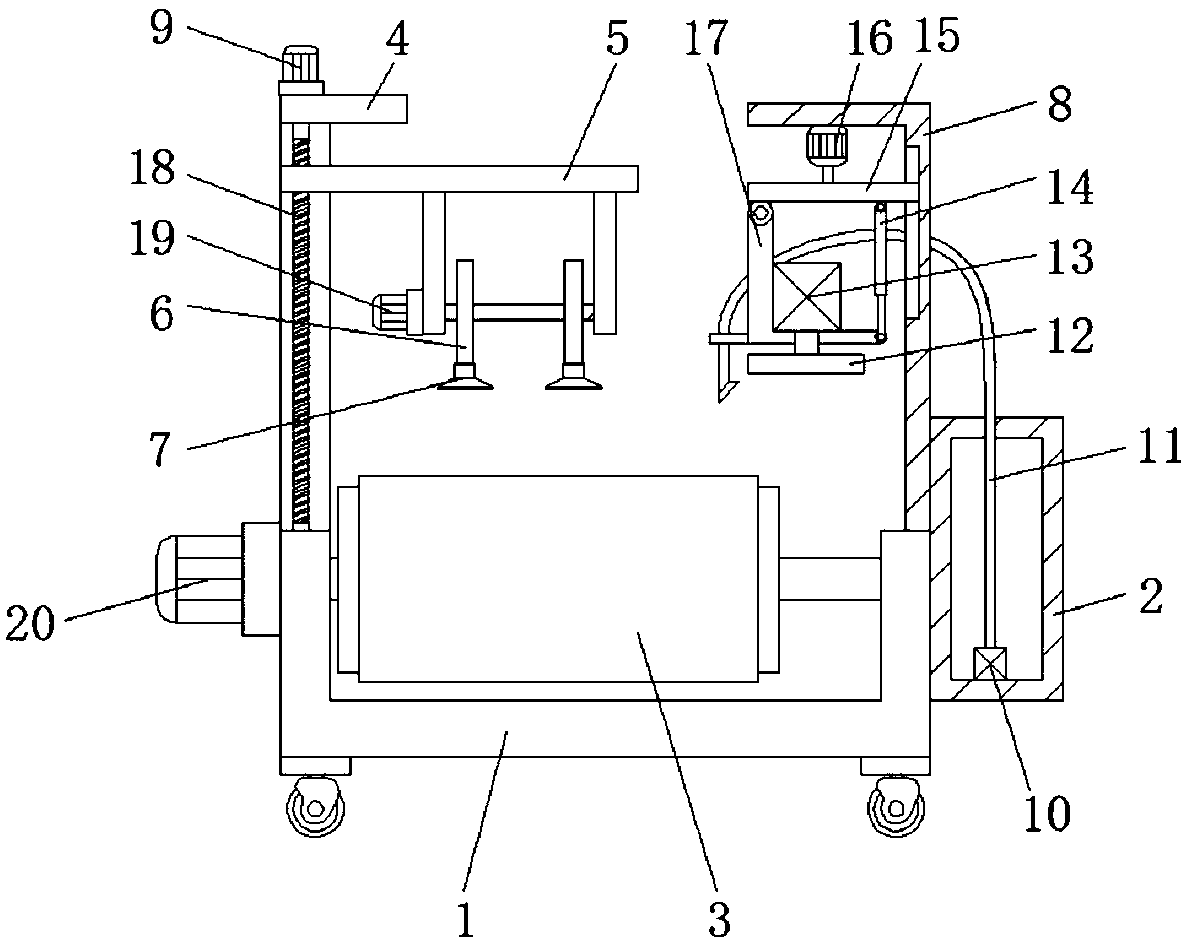
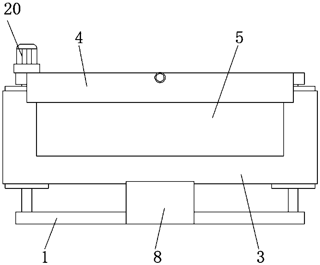
[0022] refer to Figure 1-3 , a glass chamfering device that is easy to adjust, includes a frame 1, and both sides of the outer wall of the frame 1 are provided with pulley shaft mounting holes, and the inner walls of the two pulley shaft mounting holes are connected with pulley shafts through bearings, two One side outer wall of the pulley shaft is connected with a pulley through a key, and the same conveyor belt 3 is sleeved on one side outer wall of the two pulleys, and the one side outer wall of the frame 1 is fixed with a drive motor 20 by screws, and the drive motor 20 The output shaft is fixed on the outer wall of one end of the pulley shaft through a coupling...


PUM


Abstract

The invention discloses a glass chamfering device convenient to adjust. The glass chamfering device comprises a machine frame; the two sides of the outer wall of the machine frame are provided with belt pulley shaft installation holes, and the inner walls of the two belt pulley shaft installation holes are connected with belt pulley shafts through bearings; the outer walls of one sides of the twobelt pulley shafts are connected with belt pulleys through keys, and the outer walls of one sides of the two belt pulleys are sleeved with the same conveying belt; a driving motor is fixed to the outer wall of one side of the machine frame through screws, and an output shaft of the driving motor is fixed to the outer wall of one end of the corresponding pulley shaft through a coupling; universal wheels are fixed to the four corners of the outer wall of the bottom of the machine frame through screws; and a supporting frame is fixed to one side of the outer wall of the top of the machine frame through screws. According to the glass chamfering device convenient to adjust, the angle and height of a polishing wheel can be adjusted, the chamfering angle and size can be conveniently adjusted, theoperation convenience is advantageously improved, moving of glass is not disturbed while the stability of the glass is improved, polishing chippings can be removed in time, and the chamfering machining quality is advantageously improved.

Description

technical field [0001] The invention relates to the technical field of glass production devices, in particular to an adjustable glass chamfering device. Background technique [0002] Glass chamfering machine is one of the commonly used equipment for glass production. After the glass is produced, it needs to be chamfered according to the requirements. The quick and convenient use of glass chamfering equipment will directly affect the production speed of glass. The design of glass chamfering equipment is not good. Reasonable, inconvenient to use, will increase the chamfering time and affect the efficiency. [0003] In the current glass chamfering processing technology, the traditional manual chamfering method is generally used, but the manual chamfering method usually has imprecise chamfering, difficult to control the size, and the chamfering effect is often uneven due to the technical level of the processor. At the same time, some automatic chamfering technologies have also ...

Claims


Application Information

Patent Timeline
IPC IPC(8): B24B9/08B24B41/02B24B41/06B24B41/00B24B55/02
CPCB24B9/08B24B41/005B24B41/02B24B41/06B24B55/02
Inventor 不公告发明人
Owner 福建省三林生态科技有限公司
Learn More