
Thin-wall barrel nesting device

A technology of thin-walled cylinders and suits, which is applied in the direction of hand-held tools and manufacturing tools, can solve the problems of long production cycle, easy deformation, large deformation, etc., and achieve the goals of reducing labor intensity, high degree of automation, and improving the quality of suits Effect

Active Publication Date: 2018-11-02
CSIC PRIDENANJINGINTELLIGENT EQUIP SYST CO LTD
View PDF7 Cites 2 Cited by
  • Summary
  • Abstract
  • Description
  • Claims
  • Application Information

AI Technical Summary

Problems solved by technology

Artificial suiting is to deform the inner cylinder by artificially applying external force to achieve the effect of shrinking the diameter of the inner cylinder, and then through the auxiliary suit tooling, the deformed and shrunk inner cylinder is inserted into the outer cylinder by means of horizontal and horizontal socketing. This production method has a long production cycle, a large number of personnel, and the quality of the suit cannot be controlled; the mechanical suit also uses this horizontal inserting method to add chamfers at the port of the inner cylinder in advance, fix the outer cylinder, and apply external force to the inner cylinder. Forcibly push the inner cylinder into the outer cylinder, but because the thin-walled cylinder itself is thin, it is easy to deform. If the horizontal set is adopted, the deformation of the cylinder will be large after the force is applied, and the pushing resistance during the set process is extremely high. Large, unable to meet the production process requirements of the thin-walled cylinder set

Method used


Image

  • Thin-wall barrel nesting device
  • Thin-wall barrel nesting device
  • Thin-wall barrel nesting device

Examples


Embodiment Construction

[0019] The technical solution of the present invention will be further described in detail below according to the embodiments and the accompanying drawings.

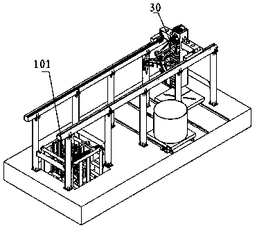
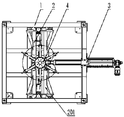
[0020] Such as figure 1 , figure 2 As shown, a thin-walled cylinder assembly device includes a set unit 101 and a transfer device 30, the transfer device 30 is arranged above the set unit 101, and the set unit 101 includes a frame 1, a jacking mechanism 2, Side pressing mechanism 3, telescopic lining mechanism 4, said telescopic lining mechanism 4 is arranged at the bottom of frame 1, said jacking mechanism 2 includes a pair of jacking assemblies 201 symmetrically arranged on both sides of telescopic lining mechanism 4 , the pair of jacking assemblies 201 are respectively connected to the upper and lower sides of the frame 1 , and the side pressing mechanism 3 is connected to the right side of the frame 1 .

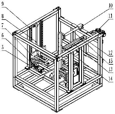
[0021] Such as image 3 As shown, the jacking assembly 201 includes a mounting seat 5, a first reduction moto...


PUM


Abstract

The invention relates to the technical field of thin-wall barrel nesting device, comprising a nesting unit and a transferring device arranged above the nesting unit. The nesting unit comprises a rack,a lifting mechanism, a side pressing mechanism and a retractable inner-support mechanism. The retractable inner-support mechanism is arranged at the bottom of the rack; the lifting mechanism comprises a pair of lifting assemblies arranged at two sides of the retractable inner-support mechanism symmetrically and respectively connected with two side surfaces of the rack; the side pressing mechanismis connected to the position, adjacent to the lifting assemblies, of the rack. According to the characteristic that thin-wall barrels are easy to deform, the thin-wall barrel nesting device utilizesa inside-to-outside vertical nesting mode to complete nesting of the barrels automatically; with the inner supporting and outer pressing during nesting, work efficiency in nesting of the thin-wall barrels is improved greatly. The thin-wall barrel nesting device has the advantages of compact and simple structure, high automation level, and capability of reducing labor intensity of workers and improving nesting quality of the thin-wall barrels.

Description

technical field [0001] The present invention relates to the technical field of thin-wall cylindrical casing equipment, in particular to the technical field of thin-wall cylindrical casing equipment. Background technique [0002] At present, the production methods of the known composite thin-walled cylinder suits mainly include manual suits and mechanical suits. Artificial suiting is to deform the inner cylinder by artificially applying external force to achieve the effect of shrinking the diameter of the inner cylinder, and then through the auxiliary suit tooling, the deformed and shrunk inner cylinder is inserted into the outer cylinder by means of horizontal and horizontal socketing. This production method has a long production cycle, a large number of personnel, and the quality of the suit cannot be controlled; the mechanical suit also uses this horizontal inserting method to add chamfers at the port of the inner cylinder in advance, fix the outer cylinder, and apply exte...

Claims


Application Information

Patent Timeline
Patent Type & Authority Applications(China)
IPC IPC(8): B25B27/06
CPCB25B27/06Y02E30/30
Inventor 吕洪光刘伟连王新祥苑留堂陈建
Owner CSIC PRIDENANJINGINTELLIGENT EQUIP SYST CO LTD
Learn More