Automatic slurry shaking machine and method for manufacturing artwork by adopting automatic slurry shaking machine

A shaker and automatic technology, applied in the field of handicraft manufacturing equipment and handicraft production, can solve the problems of low efficiency, unstable quality of finished products, high labor intensity, etc., and achieve the effects of saving human resources, simple structure and improving efficiency.

Pending Publication Date: 2018-11-02
许显日
View PDF0 Cites 3 Cited by
  • Summary
  • Abstract
  • Description
  • Claims
  • Application Information

AI Technical Summary

Problems solved by technology

[0005] The present invention aims at the problems of high labor intensity, low efficiency and unstable quality of finished products in manual operation in the prior art, and now provides an automatic shaker, which automates the shake and vacuum process, improves production efficiency, and reduces work intensity , while increasing the product yield

Method used


Image

  • Automatic slurry shaking machine and method for manufacturing artwork by adopting automatic slurry shaking machine
  • Automatic slurry shaking machine and method for manufacturing artwork by adopting automatic slurry shaking machine
  • Automatic slurry shaking machine and method for manufacturing artwork by adopting automatic slurry shaking machine

Examples


Embodiment 1

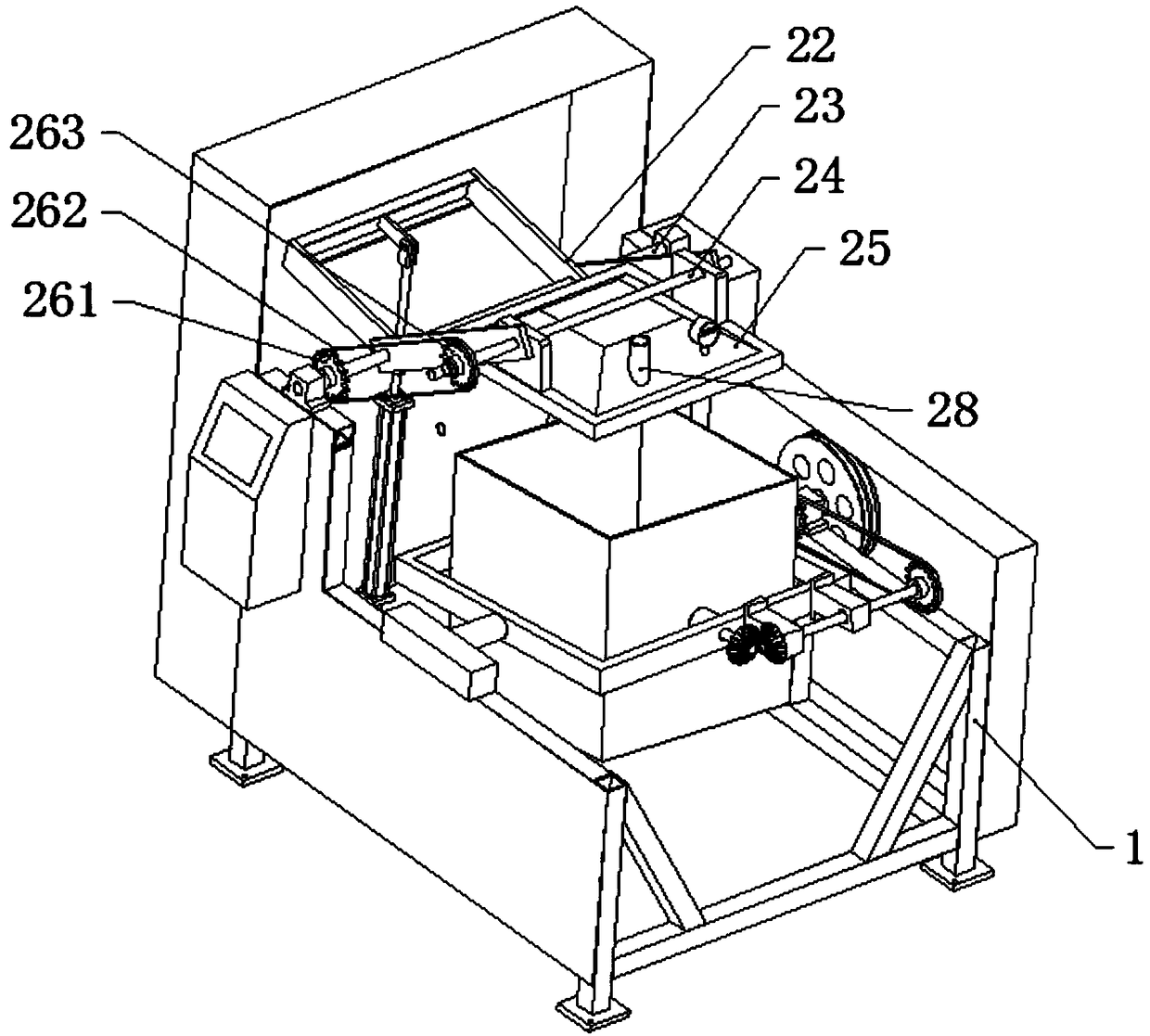
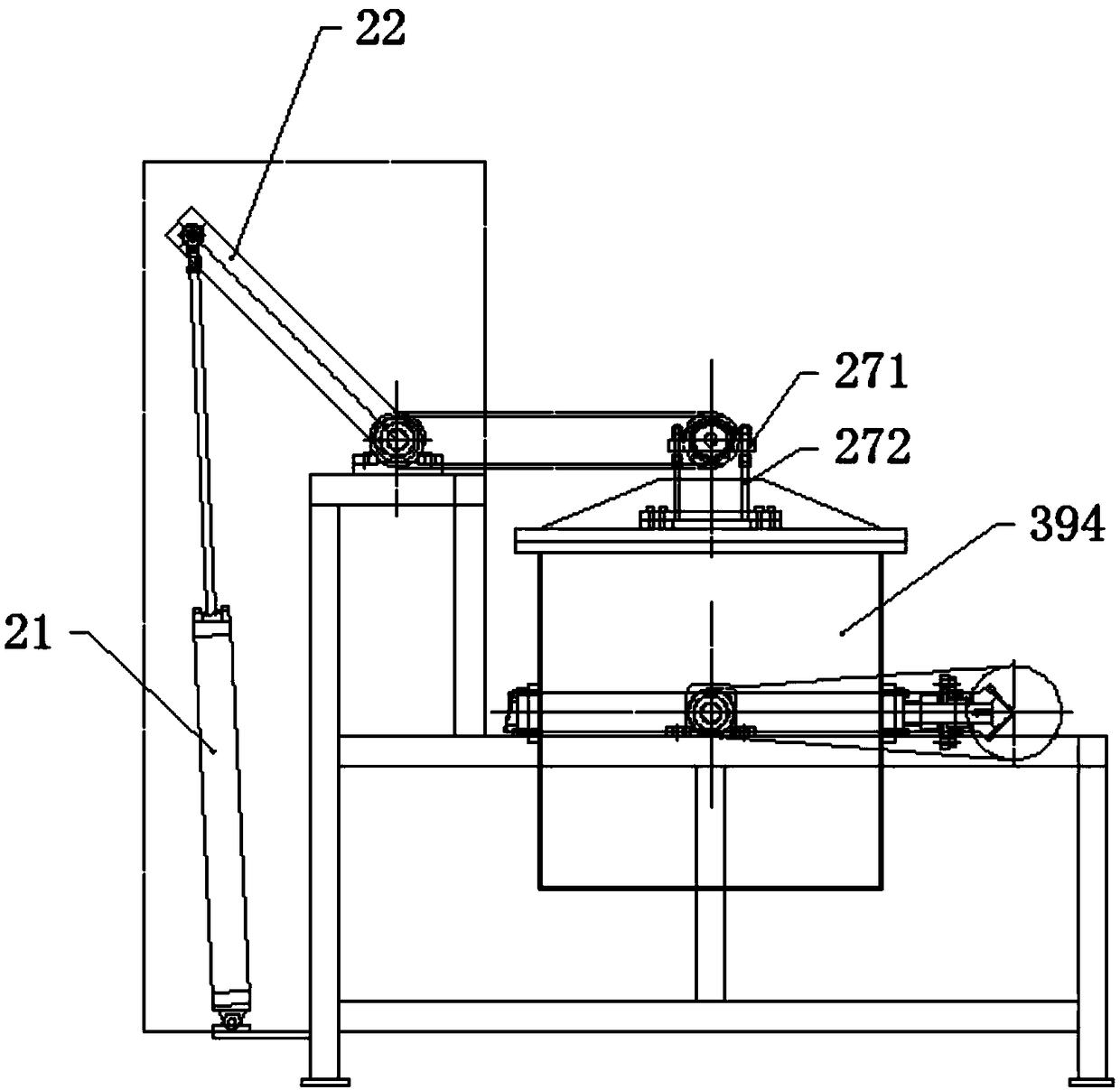
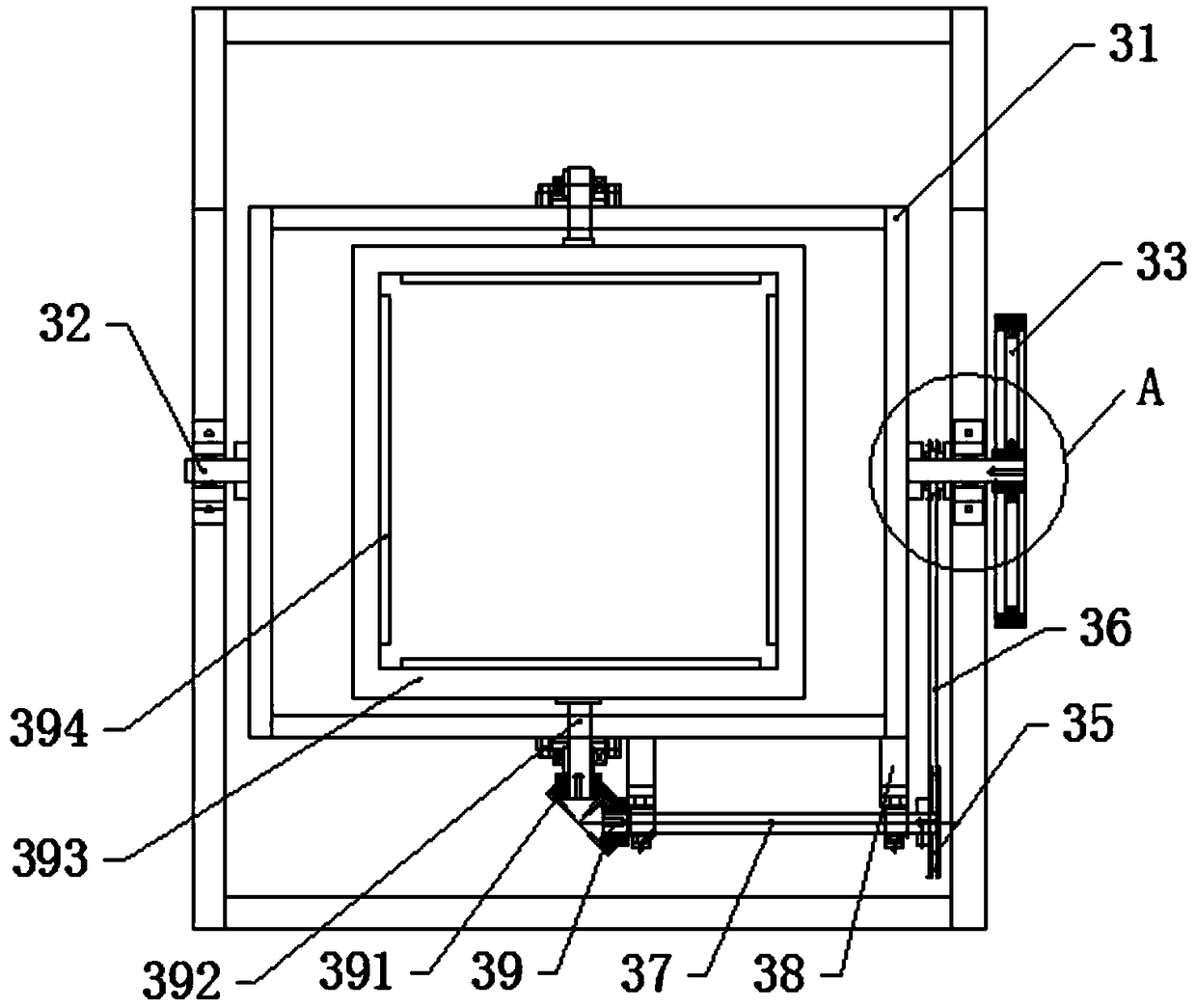
[0035] like Figure 1 to Figure 4 As shown, an automatic shaker includes a frame 1, on which a vacuum tank upper cover 25 is fixedly provided with an opening and closing mechanism 2, a vacuum tank body rotating structure 3, and the vacuum tank body rotating structure 3 is provided Below the opening and closing mechanism 2 of the upper cover 25 of the vacuum tank, it also includes a variable frequency brake motor and a PLC.

[0036] Wherein, the opening and closing mechanism 2 of the vacuum tank upper cover 25 includes a main rotating drive mechanism 21, a main rotating shaft 23, a rotating arm support 22, a secondary rotating small shaft 24, and a vacuum tank upper cover 25, and the rotating arm support 22 is V The main rotating shaft 23 is fixedly connected to the middle intersection of the rotating arm bracket 22, the main rotating shaft 23 is fixed on the frame 1 through a bearing, and one end of the rotating arm bracket 22 is rotatably connected to the extension of the mai...


PUM


Abstract

The invention provides an automatic slurry shaking machine and a method for manufacturing an artwork by adopting the automatic slurry shaking machine. The machine comprises a machine frame, a vacuum tank upper cover opening and closing mechanism and a vacuum tank body rotating structure are fixedly arranged on the machine frame, the vacuum tank body rotating structure is arranged below the vacuumtank upper cover opening and closing mechanism, the machine further comprises a variable-frequency brake motor connected with the vacuum tank body rotating structure, and the variable-frequency brakemotor is connected with a PLC. A vacuum tank main box body can rotate in two directions, the machine replaces manpower operation, time is saved, manpower resources are saved, the working intensity ofworkers is greatly relieved, the rate of finished products is improved, the yield is improved, and the benefits are improved; the vacuum cover opening and closing mechanism is simple in structure anddoes not occupy space on the premise that a cover opening and closing function is met, particularly under the condition of closing a cover for vacuumizing, cover closing is sealed and tightly closed;and a rotating mechanism of a vacuum box body can achieve 360-degree omni-directional three-dimensional rotation, the rotation speed can be adjusted, and the slurry shaking success rate of the artworks with different sizes and volumes in a mold cavity is greatly improved.

Description

technical field [0001] The invention belongs to the technical field of handicraft manufacturing equipment, in particular to an automatic shaker. [0002] The invention belongs to the field of handicraft production, and particularly relates to a method for producing handicrafts by using an automatic shaker. Background technique [0003] In the process of making handicrafts, after manually pouring the fluid-like raw materials into the mold and plugging the inlet and outlet, in the time period when the fluid-like raw materials gradually harden, in order to reduce the bubbles on the outer surface of the handicrafts, it is necessary to put the mold The mold is placed in a vacuum environment to remove the tiny air bubbles in the raw materials. Therefore, during the production process, it is necessary to put it into a vacuum tank to draw a vacuum, and then take out the mold, and then manually put the mold into the workbench. Flip the mold up or down, or left or right to shape the ...

Claims


Application Information

Patent Timeline
Patent Type & Authority Applications(China)
IPC IPC(8): B44C5/00B28B3/00B28B17/00D21J3/00B29C39/22B29C39/42
CPCB28B3/006B28B17/00B29C39/22B29C39/42B44C5/00D21J3/00Y02P70/10
Inventor 许显日
Owner 许显日
Why Eureka
Try Eureka