
Lifting device of track crane and method for replacing traveling wheel of track crane

A technology for lifting devices and rail cranes, which is applied to the lifting device of rail cranes and the replacement of traveling wheels of rail cranes. It can solve the problems of potential safety hazards, weak traveling wheel brackets, and damage to crane guide rails, etc., and achieves a fast lifting process. Stability, eliminating the need for hydraulic piping systems, and improving safety

Pending Publication Date: 2018-11-02
FAW VOLKSWAGEN AUTOMOTIVE CO LTD
View PDF8 Cites 1 Cited by
  • Summary
  • Abstract
  • Description
  • Claims
  • Application Information

AI Technical Summary

Problems solved by technology

Using this emergency repair method, it takes up to 50 minutes to find a suitable hanging point for installation, use, and disassembly of the chain hoist during the emergency repair process. The single emergency repair time is as long as 80 minutes, and the output loss is 85 units / time
In practice, in many cases, the site space is narrow, resulting in inconvenient installation of slings and chain hoists, and difficult repairs
And, because the hand chain hoists are relatively heavy, there are potential safety hazards
[0004] Of course, it can also be realized by a hydraulic jack, but two jacks are required to be used together, and the installation and disassembly time is reduced to 30 minutes, but the traveling wheel bracket is weak and cannot support the weight of the crane, so it is not suitable to use
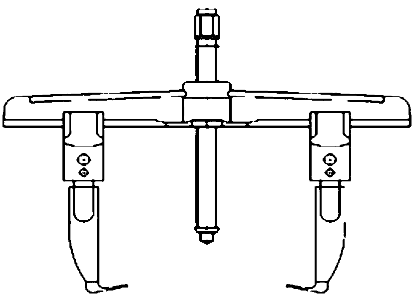
can also be used as figure 2 The mechanical two-claw stroker shown above, but its disadvantages are that it is laborious to lift, the thread of the screw is easily deformed under a large force, there is a risk of fracture during use, and the service life is short; the conical top of the screw damages the guide rail of the crane, so it is not suitable for use

Method used


Image

  • Lifting device of track crane and method for replacing traveling wheel of track crane
  • Lifting device of track crane and method for replacing traveling wheel of track crane
  • Lifting device of track crane and method for replacing traveling wheel of track crane

Examples


Embodiment Construction

[0038] In order to make the purpose, technical solutions and advantages of the present invention clearer, the technical solutions in the embodiments of the present invention will be clearly and completely described below in conjunction with the accompanying drawings in the embodiments of the present invention. Obviously, the described embodiments are only Some, but not all, embodiments of the invention. Based on the embodiments of the present invention, all other embodiments obtained by persons of ordinary skill in the art without making creative efforts belong to the protection scope of the present invention.

[0039] In describing the present invention, it should be understood that the terms "X axis", "Y axis", "Z axis", "perpendicular", "parallel", "upper", "lower", "front", "rear", "left" , "right", "vertical", "horizontal", "top", "bottom", "inner", "outer" and other indicated orientations or positional relationships are based on the orientations or positional relationshi...


PUM


Abstract

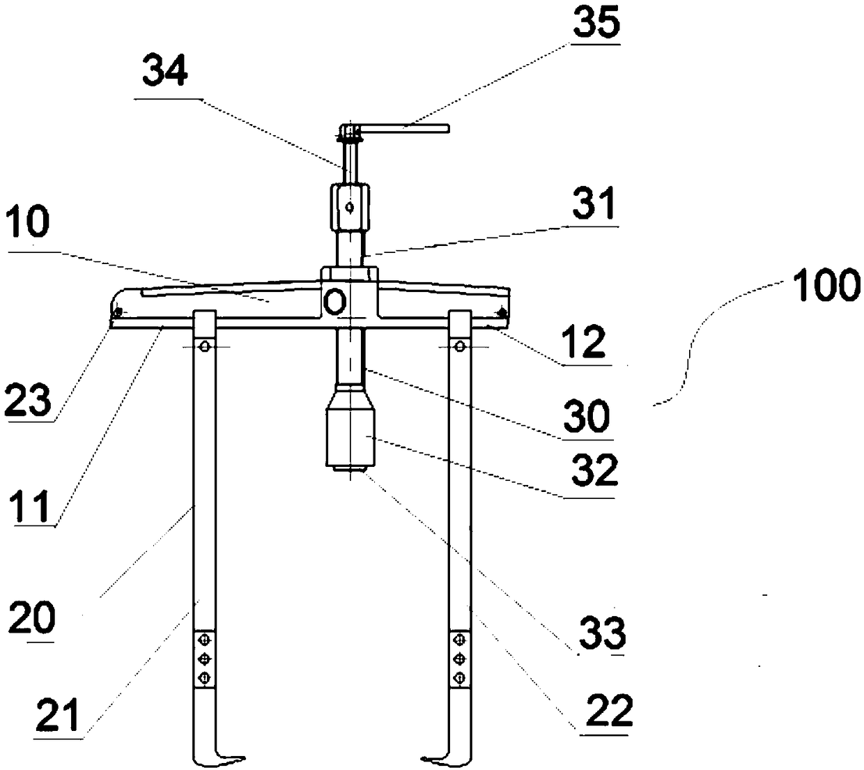
The invention discloses a lifting device of a track crane and a method for replacing a traveling wheel of the track crane, and belongs to the field of hoisting. The lifting device comprises a bearingbody, a clamping assembly movably connected to the lower portion of the bearing body and a power assembly vertically connected with the bearing body; the clamping assembly at least comprises a first clamping arm and a second clamping arm which are arranged in pairs and are adjustable in distance; the bearing body comprises a first sliding track and a second sliding track which are arranged at thetwo sides of the bearing body and matched with the first clamping arm or the second clamping arm, the second sliding track is located at one side of a side beam, and the length of the first sliding track is larger than that of the second sliding track; the power assembly comprises a transmission piece perpendicular to the bearing body and a booster fixedly arranged at one end of the transmission piece; when the track crane is lifted, the booster abuts against a guide track to lift the track crane to be separated from the guide track. According to the lifting device, through the arrangement ofthe asymmetric sliding tracks at the two sides, the total weight can be controlled while the balance is ensured, it is ensured that one person can take, install, use and disassemble the lifting device.

Description

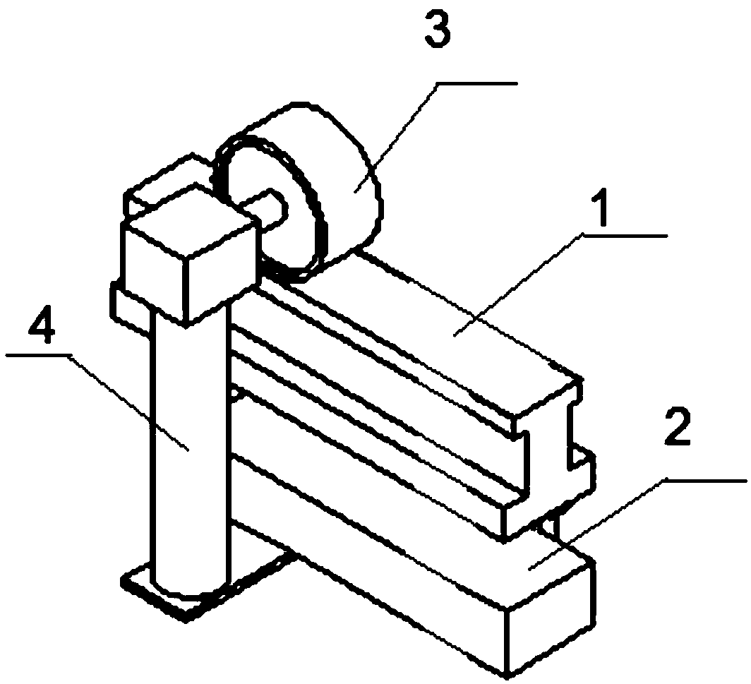
technical field [0001] The invention relates to the field of hoisting, in particular to a lifting device of a rail crane and a method for replacing traveling wheels of the rail crane. Background technique [0002] At present, the assembly workshops of automobile manufacturers generally use EHB rail cranes to lift the car body to assist in the assembly work. Such as figure 1 Shown is a partial structural diagram of the EHB rail crane, which relies on the guide rail 1 and moves along the guide rail 1. The EHB rail crane includes a crossbeam 2 , a traveling wheel 3 rollingly connected to the upper surface of the guide rail 1 , and a side beam 4 connected between the crossbeam 2 and the traveling wheel 3 . During normal operation, the traveling wheel 3 and the guide rail 1 are always in a tight or clamped connection state. The surface of the walking wheel 3 is generally covered with a rubber layer, which is prone to damage and needs to be replaced frequently. [0003] When t...

Claims


Application Information

Patent Timeline
Patent Type & Authority Applications(China)
IPC IPC(8): B66F3/00B66C1/42
CPCB66C1/42B66F3/00
Inventor 王清羽姚文涛秦杰林申龙彭长风王聪
Owner FAW VOLKSWAGEN AUTOMOTIVE CO LTD
Learn More