Knitting machine dust removing device capable of lifting and changing rotating angle

A technology of rotation angle and dust removal device, applied in knitting, textile and paper making, etc., can solve the problems affecting dust removal effect and product quality, occupying space, disorder and other problems, and achieve the effect of protecting health, low noise and ensuring product quality.

Pending Publication Date: 2018-11-02
YANCHENG WANDALI KNITTING MACHINERY
View PDF9 Cites 1 Cited by
  • Summary
  • Abstract
  • Description
  • Claims
  • Application Information

AI Technical Summary

Problems solved by technology

The defect of this dust removal method is obvious. Since there are as many as 6 to 8 dust removal fans in this type of device, it not only takes up a lot of space above the machine table, but also appears messy, and produces a lot of noise during operation, and consumes a lot of energy. more power
More importantly, during the operation of the knitting machine, the yarn wool on the surface of the textile raw material will be scattered around during the weaving process and attached to different parts of the loom at different heights, while the traditional dust removal device cannot be moved up and down due to its fixed position. Mobile, so it can only remove dust from a fixed part, which greatly affects the dust removal effect and product quality

Method used


Image

  • Knitting machine dust removing device capable of lifting and changing rotating angle
  • Knitting machine dust removing device capable of lifting and changing rotating angle
  • Knitting machine dust removing device capable of lifting and changing rotating angle

Examples


Embodiment Construction

[0030] The following examples are further explanations and supplements to the present invention, and do not constitute any limitation to the present invention.

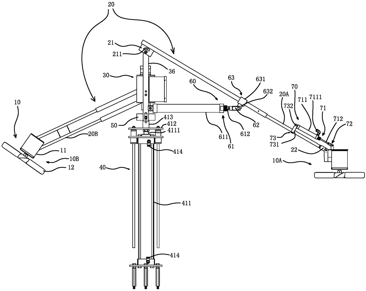
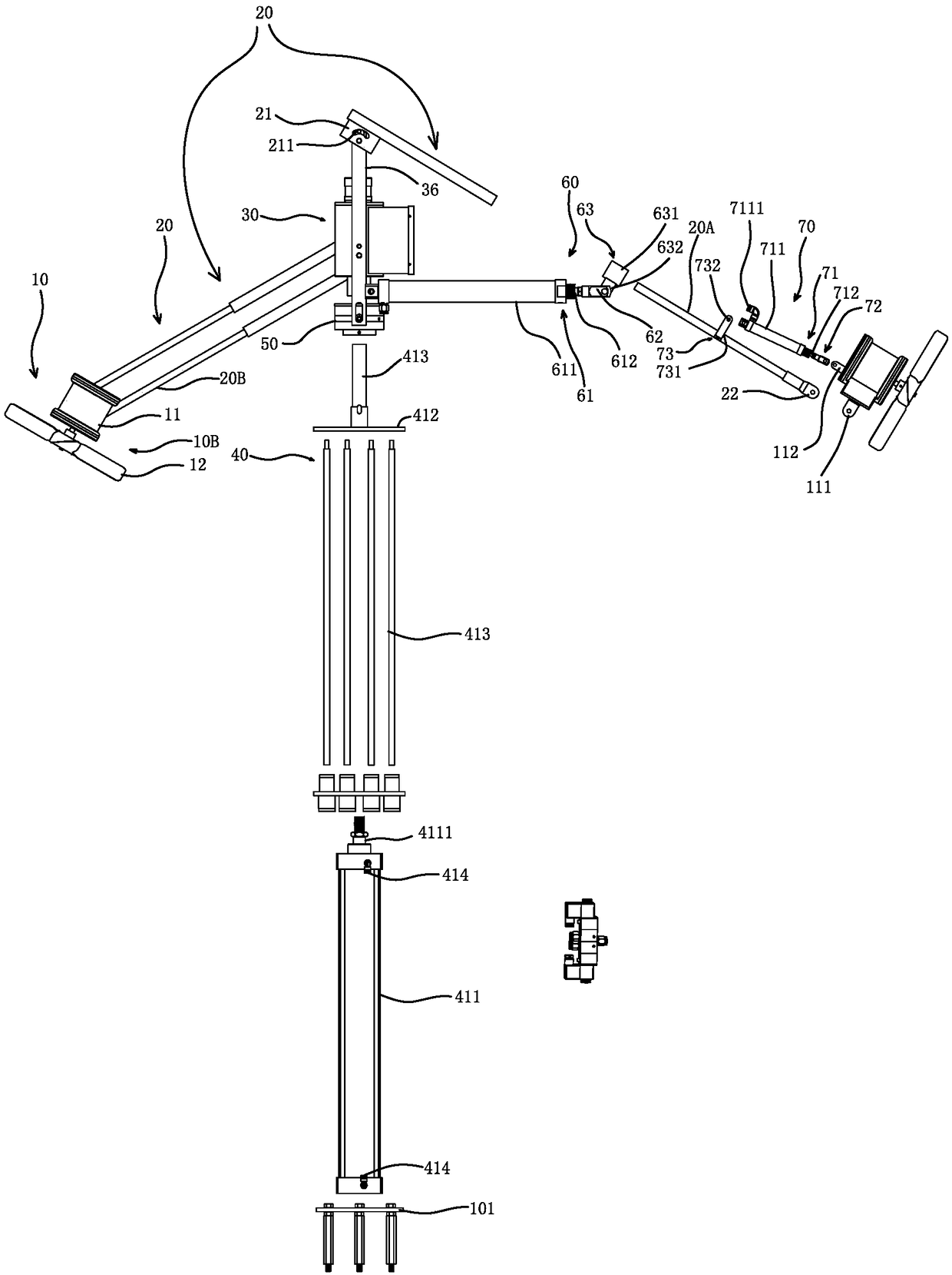
[0031] see figure 1 , figure 2 , the dust removal device for knitting machines that can lift and change the rotation angle of the present invention includes at least one set of dust removal fans 10, fan connecting rods 20, central rotating body 30, lifting mechanism 40, air intake rotating complex 50, fan connecting rod angle change The mechanism 60 , the fan angle conversion mechanism 70 and the control mechanism 80 .

[0032] like Image 6 , Figure 7 As shown in the figure, the dust removal device for the knitting machine of the present invention, which can be raised and lowered and the rotation angle can be changed, is arranged in the center of the yarn feeder disc above the machine table of the knitting machine. D, yarn hook E and other parts to remove dust. After lifting, the air duct B and other ducts C c...


PUM


Abstract

The invention relates to a knitting machine dust-removing device capable of lifting and changing the rotating angle, which includes at least one group of dust-removing fans, and the dust-removing fanscan swing up and down by using a central rotating body as a pivot while rotating around the central rotating body along the circumferential direction to adjust the rotating angle to a set rotating angle; a lifting mechanism, wherein the lifting mechanism can push the central rotating body and the dust removing fans to move up and down to different dust removal parts of the knitting machine; an air intake rotating complex, wherein the air intake rotating complex is connected with the central rotating body and the lifting mechanism; a fan connecting rod angle changing mechanism, wherein the fanconnecting rod angle changing mechanism is respectively connected with the fan connecting rod and the air intake rotating complex; a fan angle changing mechanism, wherein the fan angle changing mechanism is respectively connected with the fan connecting rod and the dust removing fans; a control mechanism, wherein the control mechanism is respectively connected with the central rotating body, thelifting mechanism, the air inlet rotating complex, the fan connecting rod angle changing mechanism and the fan angle changing mechanism, so as to control the starting or stopping of the central rotating body, the lifting of the lifting mechanism, and the rotating angles of the fan connecting rod and the dust removing fans.

Description

【Technical field】 [0001] The invention relates to textile machinery, in particular to a dedusting fan that can be lifted up and down to the dedusting parts located at different heights according to actual needs, so as to effectively clean all the dust accumulation parts of the knitting machine, and can effectively improve the dedusting efficiency. Angled knitting machine dust collector. 【Background technique】 [0002] The knitting machine is the most commonly used weaving machine in the textile industry. The knitting machine will produce a large amount of yarn wool during the weaving process, and the yarn wool attached to the surface of the textile raw material will be scattered during the weaving process. If the yarn wool is not cleaned up in time , will accumulate on the surface of the machine and the fabric and affect the normal operation of the machine, and cause an increase in the number of processing points of the fabric, and will also pollute the knitting machine and ...

Claims


Application Information

Patent Timeline
Patent Type & Authority Applications(China)
IPC IPC(8): D04B35/32
CPCD04B35/32
Inventor 陆德泉
Owner YANCHENG WANDALI KNITTING MACHINERY
Why Eureka
Try Eureka