
Cast steel joint stress test device
A technology of cast steel joints and stress testing, applied in the field of cast steel, can solve the problems of slow testing of cast steel joints, inability to change connection holes, etc., and achieve the effects of simple structure, increased life, and strong safety
- Summary
- Abstract
- Description
- Claims
- Application Information
AI Technical Summary
Problems solved by technology
Method used
Image

Examples
Embodiment Construction
[0018] In order to make the technical means, creative features, goals and effects achieved by the present invention easy to understand, the present invention will be further described below in conjunction with specific embodiments.
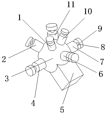
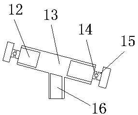
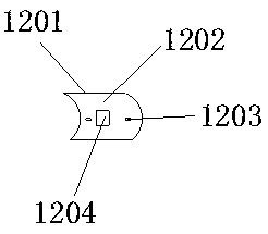
[0019] see figure 1 , figure 2 and image 3 , the present invention provides a stress testing device for cast steel nodes, the structure of which includes: a first cast steel node 1, a second cast steel node 2, a fixed sphere 3, a circular section 4, a fixed support 5, a fixed cylinder 6, a first Three cast steel nodes 7, small rolling balls 8, ring block 9, fourth cast steel nodes 10, protective cover 11, stress test device 12, cast steel inner wall 13, groove 14, spacer 15, reinforcement foot 16, all The circular section 4 is connected with the fixed cylinder 6, the fixed cylinder 6 is provided with a protective cover 11, the ring block 9 is connected with the rolling ball 8 through the pad 15, and the cast steel inner wall 13 is connected wi...
PUM
 Abstract
Description
Claims
Application Information