Optical cable retreating machine and realizing method thereof

A realization method, the technology of uncable machine, applied in the direction of light guide, optics, optical components, etc., can solve the problems of wasting manpower, prolonging time, and the cable core does not meet the requirements, so as to reduce the loss of optical fiber and uncable at a slow and constant speed , The effect of improving the cable withdrawal efficiency

Inactive Publication Date: 2018-11-02
ANHUI UNIV OF SCI & TECH
View PDF0 Cites 2 Cited by
  • Summary
  • Abstract
  • Description
  • Claims
  • Application Information

AI Technical Summary

Problems solved by technology

However, when there are disadvantages or loopholes in the processing technology, management methods, materials used, etc., it is very easy to cause the produced cable core to fail to meet the requirements.
When the above situation occurs, the traditional method is to slowly withdraw the yarn from the cable core by manual means, and then carefully collect the bundle tube. However, this manual method is not only inconvenient to operate, wastes manpower, Prolong the time, and the small yarn is easy to get into the hands, and the manual operation is easy to bend the bundle tube, resulting in a failure

Method used


Image

  • Optical cable retreating machine and realizing method thereof
  • Optical cable retreating machine and realizing method thereof
  • Optical cable retreating machine and realizing method thereof

Examples


Embodiment Construction

[0022] The technical solutions in the embodiments of the present invention will be clearly and completely described below in conjunction with the accompanying drawings in the embodiments of the present invention. Obviously, the described embodiments are only a part of the embodiments of the present invention, rather than all the embodiments. Based on the embodiments of the present invention, all other embodiments obtained by those of ordinary skill in the art without creative work shall fall within the protection scope of the present invention.

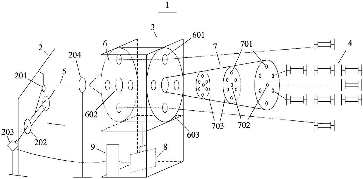
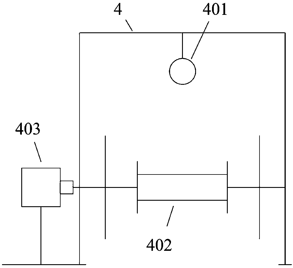
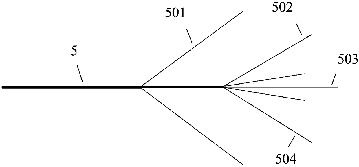
[0023] See Figure 1-4 , The present invention provides a technical solution: an optical cable unwinding machine and its implementation method, comprising a cable unwinding device main body 1 provided with a pay-off rack 2, a twisting off rack 3, and a wire take-up rack 4 and the optical fiber into a cable 5; a pay-off reel 202 is installed in the middle of the pay-off rack 2, the upper part of the twist-off rack 3 is provided with a twi...


PUM


Abstract

The invention discloses an optical cable retreating machine and a realizing method thereof. The optical cable retreating machine comprises an optical cable retreating device body. The optical cable retreating device is provided with a pay-off frame, a stranding-off frame, a cable receiving frame and an optical fiber finished cable. The middle position of the pay-off frame is provided with a pay-off disc. The upper part of the stranding-off frame is provided with a stranding-off disc, and the lower part is provided with a stranding-off motor and a controller. The middle position of the cable receiving frame is provided with a cable receiving disc. One end of the cable receiving disc is connected with a cable receiving motor. The cable receiving motor is electrically connected with the controller. The controller is electrically connected with a touch screen and a starting/stopping switch. The body structure of the optical fiber finished cable comprises yarns, an optical fiber bundle pipe, a reinforcing member and a filling rope. The optical cable retreating machine and the realizing method realize high stability and high reliability in actual use and realize an intelligent cable retreating function of the optical fiber finished cable. Furthermore the optical cable retreating machine and the realizing method thereof have advantages of convenient operation, time-saving and labor-saving function, high safety and high reliability. No bundle pipe bending is caused in the cable retreating process, and cable retreating efficiency is improved. The optical cable retreating machine andthe realizing method thereof are suitable for popularization.

Description

Technical field [0001] The invention relates to the related technical field of optical fiber and optical cable manufacturing equipment, in particular to an optical cable unwinding machine and an implementation method thereof. Background technique [0002] In the production process of optical fiber cables such as ADSS, the cable core is needed. The cable core is made by twisting the fiber bundle tube and the filling rope on the reinforcement according to the set twisting angle and quantity through the SZ twisting device. , And use yarn to tie tightly. However, when there are defects or loopholes in the processing technology, management methods, materials used and other processes, it is very easy to cause the cable core produced to fail to meet the requirements. When the above situation occurs, the traditional method is to manually withdraw the yarn from the cable core in a spiral manner, and then carefully collect the bundle tube. However, this manual method is not only inconveni...

Claims


Application Information

Patent Timeline
Patent Type & Authority Applications(China)
IPC IPC(8): G02B6/44
CPCG02B6/4479
Inventor 周扬锋陈林松陈雪健杨睿扬汪彤彤
Owner ANHUI UNIV OF SCI & TECH
Why Eureka
Try Eureka