Telecentric lens

A telecentric lens and lens technology, applied in optical components, optics, instruments, etc., can solve problems such as uneven weight distribution and low magnification, and achieve good imaging quality, high magnification, and reduced field curvature.

Pending Publication Date: 2018-11-02
舜宇光学(中山)有限公司
View PDF0 Cites 4 Cited by
  • Summary
  • Abstract
  • Description
  • Claims
  • Application Information

AI Technical Summary

Problems solved by technology

Existing telecentric lenses suffer from low magnification, structurally uneven weight

Method used


Image

  • Telecentric lens
  • Telecentric lens
  • Telecentric lens

Examples


Embodiment Construction

[0055] In order to more clearly describe the embodiments of the present invention or the technical solutions in the prior art, the following will briefly introduce the drawings that are used in the embodiments. Apparently, the drawings in the following description are only some embodiments of the present invention, and those skilled in the art can also obtain other drawings according to these drawings without creative efforts.

[0056] When describing the embodiments of the present invention, the terms "vertical", "transverse", "upper", "lower", "front", "rear", "left", "right", "vertical", " The orientation or positional relationship expressed by "horizontal", "top", "bottom", "inner" and "outer" is based on the orientation or positional relationship shown in the relevant drawings, which are only for the convenience of describing the present invention and simplifying the description, and It is not to indicate or imply that the device or element referred to must have a particu...


PUM


Abstract

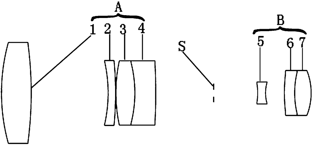
The invention relates to a telecentric lens, and the telecentric lens comprises a first lens group (A), a pupil (S), and a second lens group (B), wherein the first lens group (A), the pupil (S) and the second lens group (B) are arranged in order from an object side to an image side along an optical axis. The first lens group (A) and the second lens group (B) are both positive power lens groups. The first lens group (A) includes four lenses, and the second lens group (B) includes three lenses. The telecentric lens of the invention has the characteristics of simple structure, expandable opticalpath, high magnification, high telecentricity, low distortion and insensitivity of the optical performances of the lens to the tolerance.

Description

technical field [0001] The invention relates to the technical field of optical system and device design, in particular to a telecentric lens. Background technique [0002] The telecentric lens is widely used in workpiece size detection due to its unique parallel optical path, and is a very important optical device in the field of industrial measurement. Due to the different magnifications at different object distances, traditional industrial lenses have large perspective errors. Within a certain range of object distances, the magnification of the image remains unchanged. Existing telecentric lenses suffer from low magnification, structurally uneven weight distribution, and are susceptible to factors such as tolerances and ambient temperature. Contents of the invention [0003] An object of the present invention is to provide a telecentric lens with high telecentricity, high magnification and low distortion. [0004] To achieve the above object, the present invention prov...

Claims


Application Information

Patent Timeline
IPC IPC(8): G02B13/00G02B13/22
CPCG02B13/0015G02B13/006G02B13/22
Inventor 蓝岚聂路鑫梁伟朝邹文镔
Owner 舜宇光学(中山)有限公司
Why Eureka
Try Eureka