Outdoor power distribution cabinet

A power distribution cabinet and outdoor technology, applied in substation/power distribution device housing, electrical components, substation/switch layout details, etc., can solve the problem of not being able to block the fire source at the first time, short-circuit spontaneous combustion of internal components, poor heat dissipation, etc. problem, to achieve good heat dissipation effect, solve spontaneous combustion, and high safety effect

Inactive Publication Date: 2018-11-02
长顺县长征电器有限公司
View PDF8 Cites 5 Cited by
  • Summary
  • Abstract
  • Description
  • Claims
  • Application Information

AI Technical Summary

Problems solved by technology

The heat dissipation system is set on the top or bottom, and can only dissipate heat on one side, and its own heat dissipation performance is relatively poor.
[0003] In addition, the heat dissipation system in the prior art has poor heat dissipation performance for the components on the internal main board, and it is easy to accumulate heat inside. Excessive internal heat can easily cause short-circuit spontaneous combustion of internal components. Spontaneous combustion generally occurs under continuous high temperature conditions. That is, when a certain component is always in a high temperature state, if it is not cooled, spontaneous combustion is likely to occur next. In the prior art, an alarm system will be set up to detect the problem of spontaneous combustion, but the alarm can only notify the fire and not Can't stop the fire source immediately

Method used


Image

  • Outdoor power distribution cabinet
  • Outdoor power distribution cabinet
  • Outdoor power distribution cabinet

Examples


Embodiment Construction

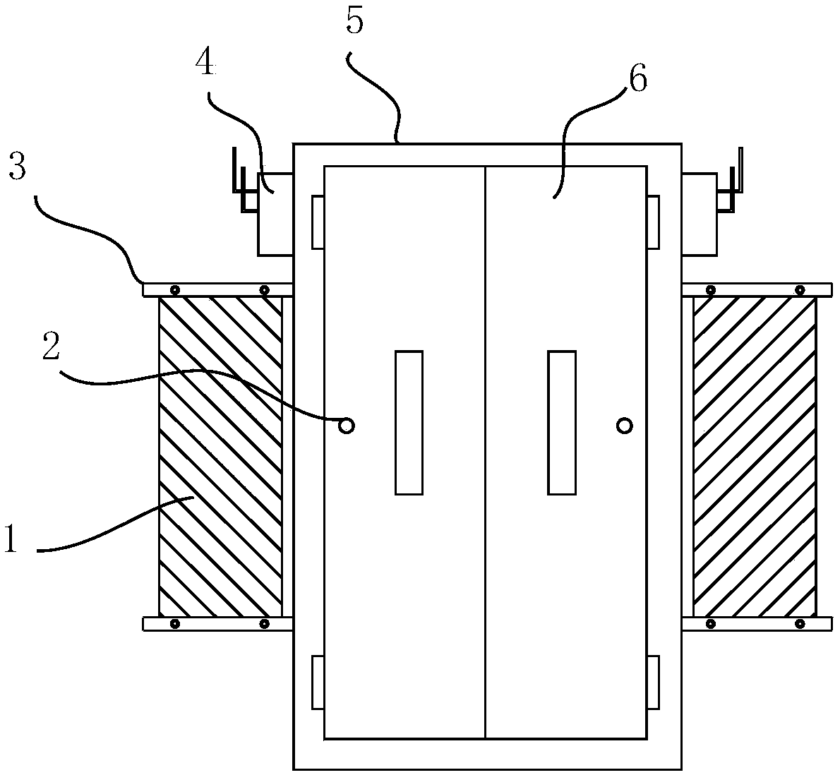
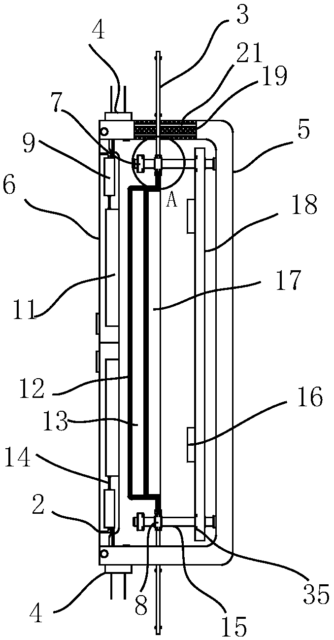
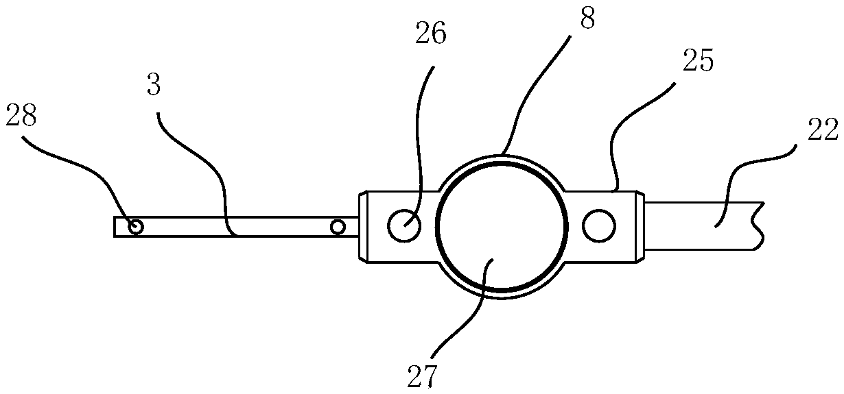
[0026] Such as figure 1 , figure 2 as well as Figure 6 As shown, the outdoor power distribution cabinet includes a cabinet body 5, the front end of the cabinet body 5 has two cabinet doors 6, an electrical chamber is arranged inside the cabinet body 5, and four positioning guide rods 15 are vertically arranged in the electrical chamber. The root of the positioning guide rod 15 is fixedly installed with a power distribution main board 18, and the side of the power distribution main board 18 opposite to the cabinet door 6 is provided with an electronic component 16, and a sliding sleeve 8 is slidably arranged on the four positioning guide rods 15, and the sliding sleeve 8 A fixing part 25 is arranged on each side, and a first magnet 26 is embedded in the outer end of the fixing part 25, and a second magnet 24 is embedded in the other side of the fixing part 25, facing the power distribution board 18 of the second magnet 24. The corresponding third magnet 35 is embedded and a...


PUM


Abstract

The invention discloses an outdoor power distribution cabinet, comprising a cabinet body, wherein the front end of the cabinet body has two cabinet doors, an electrical cavity is arranged inside the cabinet body, four positioning guide rods are vertically arranged on the bottom surface of the electric cavity, the roots of the four positioning guide rods are fixedly installed with a power distribution board, the power distribution board is provided with an electronic component on one side opposite to the cabinet doors, the four positioning guide rods are slidably provided with sliding guide sleeves respectively, and both sides of each sliding sleeve are provided with a fixed portion respectively. The invention adopts a new heat dissipation structure to replace the self-contained heat dissipation system of the power distribution cabinet, utilizes the external airflow to achieve uniform heat dissipation of the internal power distribution board, is capable of effectively absorbing heat andblocking the oxygen near the heat source when the temperature is too high for effective flame retardant, and is capable of injecting inert gas into the whole cabinet during short-circuit fire to cutoff the internal combustion conditions, thereby better protecting the entire power distribution cabinet, and enabling safer use.

Description

technical field [0001] The invention relates to an outdoor power distribution cabinet. Background technique [0002] Outdoor power distribution cabinets generally use an independent heat dissipation system. The traditional heat dissipation system generally consists of a motor and fan blades. This structure itself generates heat. However, the heat dissipation system is arranged on the top or the bottom, and can only dissipate heat on one side, and its own heat dissipation performance is relatively poor. [0003] In addition, the heat dissipation system in the prior art has poor heat dissipation performance for the components on the internal main board, and it is easy to accumulate heat inside. Excessive internal heat can easily cause short-circuit spontaneous combustion of internal components. Spontaneous combustion generally occurs under continuous high temperature conditions. That is, when a certain component is always in a high temperature state, if it is not cooled, spon...

Claims


Application Information

Patent Timeline
Patent Type & Authority Applications(China)
IPC IPC(8): H02B1/30H02B1/56H02B1/28A62C3/16A62C35/10A62C99/00
CPCA62C3/16A62C35/10A62C99/0018H02B1/28H02B1/30H02B1/565
Inventor 楼阳英
Owner 长顺县长征电器有限公司
Why Eureka
Try Eureka