Tray type bridge stand capable of being spliced

A tray type, bridge technology, applied in the direction of electrical components, etc., can solve the problems of weak bending resistance, safety hazards, increased cable laying expenses, etc., to achieve strong corrosion resistance, enhanced stability, and good general performance.

Inactive Publication Date: 2018-11-02
扬州联胜电气有限公司
View PDF0 Cites 0 Cited by
  • Summary
  • Abstract
  • Description
  • Claims
  • Application Information

AI Technical Summary

Problems solved by technology

In the prior art, the load-bearing capacity of the tray-type bridge is not very strong, and the bending resistance is relatively weak, especially the expenditure on the manufacturing cost is relatively large; therefore, technical progress and structural improvement are needed to make the cable bridge more durable It is durable and reduces its manufacturing cost; when it comes to the collection and change of cables, it is necessary to use a three-way bridge, but the design of the three-way connection parts of the three-way connection on the market is mostly right-angled, and this structure is in the laying When the cables need to be collected and changed, the cables will be bent at 90 degrees, which will easily cause the wires inside the cables to break, and the regular friction of the edges and corners of the right-angled surfaces will accelerate the wear and aging of the cables, making the cables unable to reach the theoretical service life. , to a certain extent increases the expenditure of cable laying, and there is also a great hidden danger in safety

Method used


Image

  • Tray type bridge stand capable of being spliced
  • Tray type bridge stand capable of being spliced

Examples


Embodiment Construction

[0015] A splicable tray-type bridge frame of the present invention will be described in detail below in conjunction with the accompanying drawings.

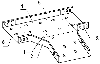
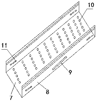
[0016] Such as figure 1 and figure 2 As shown, a splicable tray-type bridge frame includes a body seat 1 with ventilation holes at the bottom, four sets of screw holes 4 around the body seat 1, and second connecting seats 6 fixed on both sides of the body seat 1 with screws. , use screws to fix the first connecting seat 2 on the right side of the body seat 1, use screws to fix the baffle plate 5 on the left side of the body seat 1, and use fastening screws to connect the single frame on the second connecting seat 6; The single seat includes a bottom plate 7 with ventilation holes 10 at the bottom, a side plate 8 on the side of the bottom plate 7, a second connection port 11 is provided on both sides of the side plate 8, and a reinforcing rib 9 is provided outside the middle of the side plate 8; The inner side of the first conn...


PUM


Abstract

The invention provides a tray type bridge stand capable of being spliced. The tray type bridge stand comprises a body seat, four groups of screw holes, second connecting seats, a first connecting seat, a baffle plate and a single body stand, wherein ventilation holes are formed in the bottom of the body seat; the four groups of screw holes are formed in the periphery of the body seat; the second connecting seats are fixedly arranged on two sides of the body seat with screws; the first connecting seat is fixedly arranged on the right side of the body seat with screws; the baffle plate is fixedly arranged on the left side of the body seat with screws; the single body stand is connected onto the second connecting seats with fastening screws; a single body seat comprises a base plate and sideplates, ventilation holes are formed in the bottom of the base plate, the side plates are arranged on the side faces of the base plate, second connection ports are formed in two sides of the side plates, and reinforcing ribs are arranged on the outer sides of the middle parts of the side plates. The tray type bridge stand capable of being spliced provided by the invention is simple in structure, and the stability of the bridge stand is strengthened through the structures of the reinforcing ribs arranged on the side faces of the side plates; the corrosion resistance of the bridge stand is higher through electroplated zinc and hot-dip zinc sprayed on the surfaces of the connecting seats and the surface of the single body stand; and through splicing, the three-way and four-way functions can be realized, and the universal performance is good.

Description

technical field [0001] The invention relates to a tray type bridge, in particular to a splicable tray type bridge. Background technique [0002] The bridge is an essential device for cable installation. The existing tray-type bridge includes two side plates and a bottom plate arranged between the two side plates. The bottom plate is a load-bearing part for placing cables. In the prior art, the load-bearing capacity of the tray-type bridge is not very strong, and the bending resistance is relatively weak, especially the expenditure on the manufacturing cost is relatively large; therefore, technical progress and structural improvement are needed to make the cable bridge more durable It is durable and reduces its manufacturing cost; when it comes to the collection and change of cables, it is necessary to use a three-way bridge, but the design of the three-way connection parts of the three-way connection on the market is mostly right-angled, and this structure is in the laying ...

Claims


Application Information

Patent Timeline
Patent Type & Authority Applications(China)
IPC IPC(8): H02G3/04
CPCH02G3/0456H02G3/0406H02G3/0412
Inventor 尹昌圣
Owner 扬州联胜电气有限公司
Why Eureka
Try Eureka