Projection system and projection method

A projection system and projection light technology, applied in the projection system and the projection field, can solve the problem of low contrast of the projection system, and achieve the effects of reducing stray light, reducing the influence of contrast, and improving contrast

Inactive Publication Date: 2018-11-02
APPOTRONICS CORP LTD
View PDF5 Cites 6 Cited by
  • Summary
  • Abstract
  • Description
  • Claims
  • Application Information

AI Technical Summary

Problems solved by technology

[0003] In order to solve the problem of low contrast in the prior art projection system, the present invention provides a projection system and projection method with high contrast

Method used


Image

  • Projection system and projection method
  • Projection system and projection method
  • Projection system and projection method

Examples


Embodiment Construction

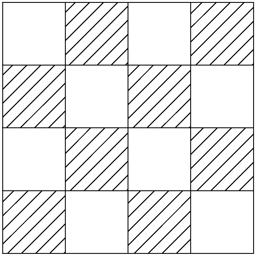
[0058] First of all, it should be noted that the contrast of a projection system usually refers to the ratio of the central illuminance value of the full white field to the central illuminance value of the full black field in a certain fixed projection screen. Usually, in a completely black field, you can directly turn off the power to falsely increase the contrast. Therefore, there is also a definition of ANSI contrast. The test method is to present 4*4 all black and all white alternately area (such as figure 1 Shown), and under this screen test to obtain ANSI contrast C R , specifically, the ANSI contrast C R conform to the following formula.

[0059]

[0060] where E bright Represents the central illuminance of the white area, E black Represents the central illuminance of the black area, E la Represents the central illuminance of the ambient light when the white area is not projected, E ba Represents the central illuminance of the ambient light when the black area ...


PUM


Abstract

The invention relates to a projection system and a projection method. The projection system comprises a signal processor, a light source, an optical relay system light emitting device and a DMD. The signal processor receives image data that comprises multiple gray-scale values, wherein each gray-scale value is corresponding to one pixel, and the signal processor also improves the gray-scale valuesof multiple pixels of the image data. The light source is used for emitting illumination light, the optical relay system provides the illumination light to the DMD, and thus the DMD can modulate to acquire projection light needed by image projection. When the gray-scale values of the multiple pixels of the image data are improved, an adjustment component turns down luminous flux of the illumination light provided to the DMD, and the decreasing proportion of the luminous flux of the illumination light is matched with the improving proportion of the gray-scale values of the image data. The DMDmodulates the adjusted illumination light according to the image data of which the gray-scale values are improved, to generate the projection light needed by image projection. The projection system isrelatively high in contrast ratio.

Description

technical field [0001] The invention relates to a projection system and a projection method. Background technique [0002] Existing projection systems generally include a light source device, a spatial light modulator (such as an LCOS spatial light modulator or a DMD spatial light modulator) and a projection lens. The light source device emits light in three colors such as red, green and blue. The image data performs image modulation on the light emitted by the light source device, and the projection lens projects the image light output by the spatial light modulator to display the projected image. However, the existing projection system may have a low contrast ratio, There is a need to improve. Contents of the invention [0003] In order to solve the problem of low contrast in the prior art projection system, the present invention provides a projection system and projection method with high contrast. [0004] A projection system comprising [0005] a signal processor, ...

Claims


Application Information

Patent Timeline
IPC IPC(8): H04N9/31G03B21/20
CPCH04N9/3155H04N9/3179G03B21/2053G03B21/00G03B21/20H04N9/3152H04N9/3158G03B21/008G03B21/208
Inventor 胡飞郭祖强杜鹏李屹
Owner APPOTRONICS CORP LTD
Why Eureka
Try Eureka