Variable angle suitcase pull bar

A suitcase and trolley technology, which is applied in the field of bags, can solve the problems of unilateral wear and inconvenient use of the pulley of the suitcase, and achieve the effect of reducing wear, reducing force and good consistency

Pending Publication Date: 2018-11-06
张凡怡
View PDF0 Cites 4 Cited by
  • Summary
  • Abstract
  • Description
  • Claims
  • Application Information

AI Technical Summary

Problems solved by technology

[0003] In order to overcome the above-mentioned inconvenient use of the existing suitcase pull rod and solve the problem of unilateral force wear on the suitcase pulley, the present invention provides a variable-angle suitcase pull rod. The suitcase trolley, the telescopic and steering of the trolley adopts a single button, push rod linkage, mechanical control lock control, the core mechanism lock modular design, simple production and assembly, good product consistency, easy after-sales maintenance, and easier push and pull use

Method used


Image

  • Variable angle suitcase pull bar
  • Variable angle suitcase pull bar
  • Variable angle suitcase pull bar

Examples


Embodiment 1

[0052] The present invention will be further described below through specific embodiments.

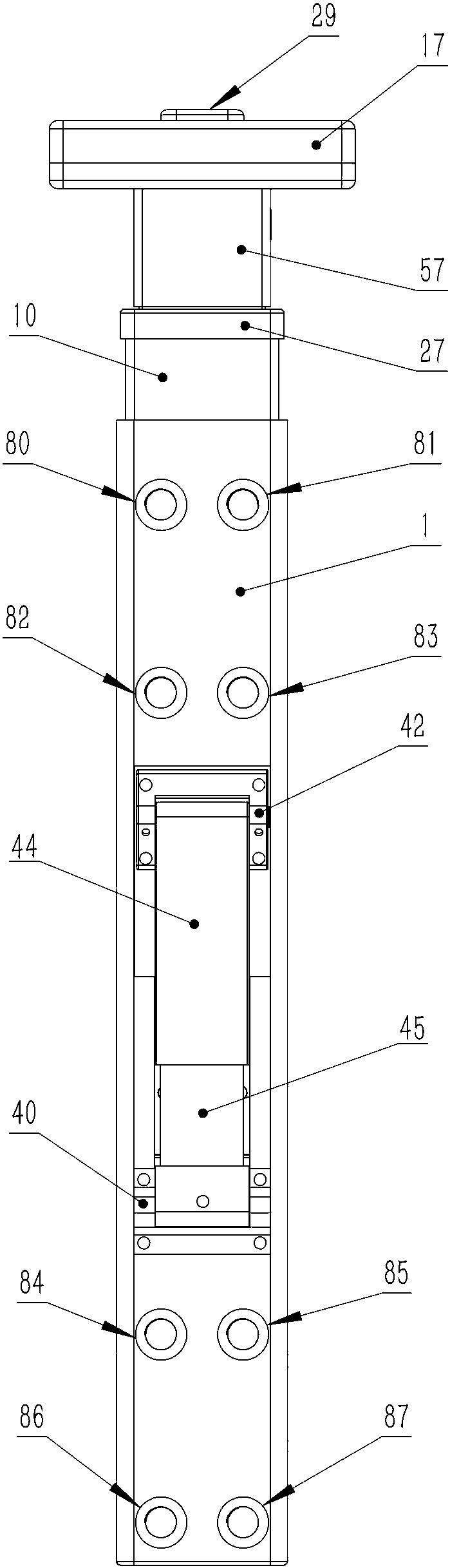
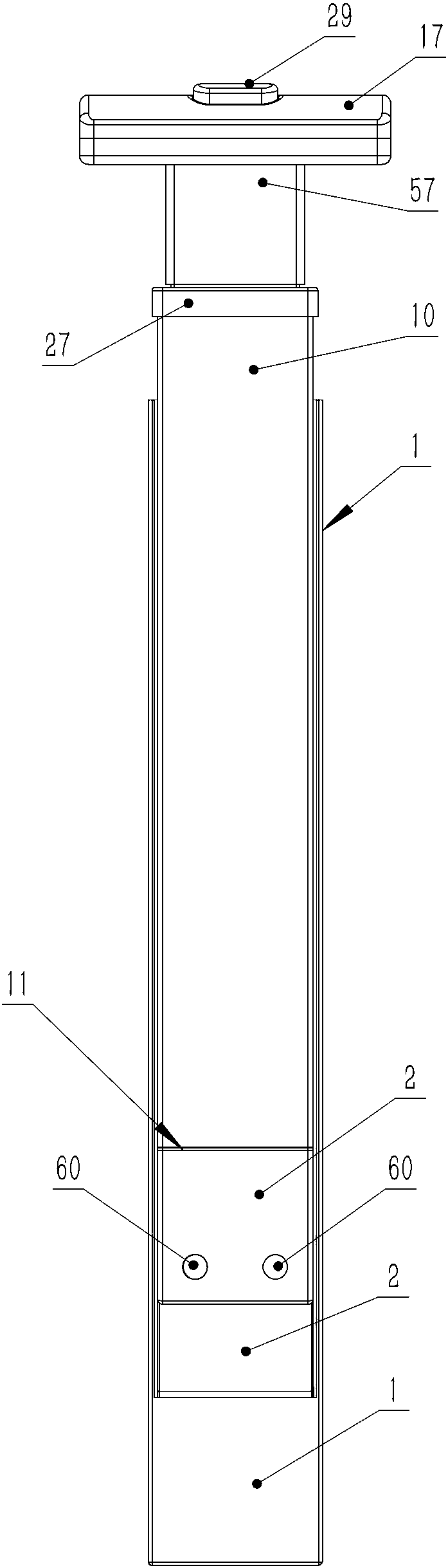
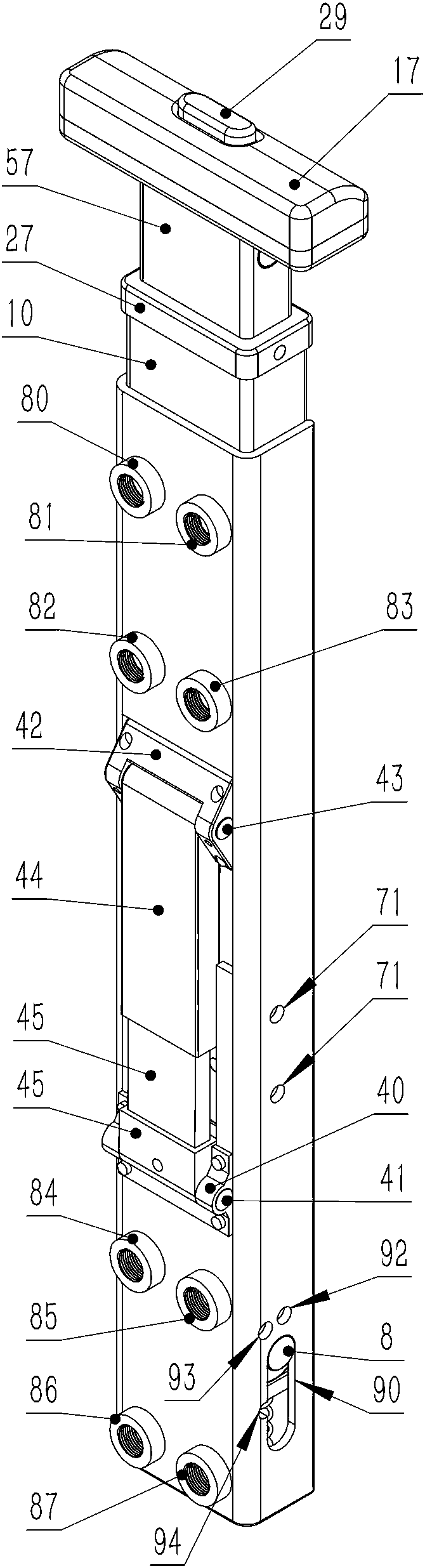
[0053] Reference Figure 1 to Figure 13 , A variable-angle suitcase pull rod, comprising a fixed pull rod housing (1), a rotating shaft housing (2), and a pull rod one (10) housing nested on the rotating shaft housing (2), a pull rod one (10) and a rotating shaft housing (2) There is an apron (11) in the joint gap between the two rods (12) is located in the shell of rod one (10), the handle bottom shell (57) of the rod is fixed to the rod two by the handle bottom shell fixing screw (24) (12) At the upper end of the housing, the handle surface shell (17) is fastened to the lever handle bottom shell (57) through the handle bottom shell fixing screw (103) and the lever button (29) is placed in the button hole of the lever handle surface shell (17) In position, there is a built-in button spring (38) in the inner center of the button (29) with one end in contact with the inner side of the butt...

Embodiment 2

[0058] Reference Figure 14 to Figure 16 , A variable-angle suitcase trolley, the structural design includes a suitcase trolley that can provide variable angles, while telescoping and adjusting the length. The extension and steering of the trolley are controlled by a mechanical control lock, and the core mechanism lock is modularized. This embodiment The difference between the second embodiment and the first embodiment is that the diagonal support sleeve and the diagonal support moving rod assembly are connected to the pull rod at an obtuse angle. The shaft end of the diagonal support sleeve is rotatably connected to the upper end of the fixed housing of the pull rod. The connection method and implementation The effect produced by the first example is similar, and the installation and fixing methods of the tie rod and the suitcase in the first and second embodiments are exactly the same.

[0059] The other structures in this embodiment are the same as those in the first embodimen...


PUM


Abstract

The invention discloses a variable angle suitcase pull bar. The structure design of the suitcase pull bar is characterized in that a variable angle can be provided, the length of the suitcase pull barcan be telescopically adjusted, the selection and positioning of the use angle of the pull bar can be completed by a pull bar rotating shaft and a positioning lock, the pull bar is provided with an inclined supporting sleeve structure, the inclined supporting sleeve automatically cooperates with the telescoping of the pull bar when the pull bar changes the angle in order to disperse the transverse stress of the pull bar, reduce the stress of the pull bar rotating shaft, avoid an overweight suitcase from damaging the pull bar and facilitate the balance and the stability of the body of the suitcase during the pushing and pulling of the heavy suitcase, the pull bar is provided with a pull bar angle control mechanism, the pull bar angle control mechanism adopts a mechanical control lock to control, and the core mechanism of the lock is modularly designed to achieve simple production installation and a good product consistence. The pull bar has the advantages of independent overall structure, simplicity in external mounting, and simplicity in after-sales maintenance, and can be used to push and pull various objects easily and conveniently.

Description

Technical field [0001] The invention relates to the field of suitcases and bags, in particular to a variable-angle suitcase pull rod that can extend and retract the length of a pull rod when pushing and pulling the suitcase, and at the same time can change the angle between the pull rod and the suitcase. Background technique [0002] At present, the well-known luggage pull rod is a push-pull pull rod device that is formed by connecting two to three telescopic tubular sleeves with each other and fixed on the shell of the luggage. When in use, the pull rod can only extend and retract in length and cannot change the angle with the suitcase. Therefore, when pushing and pulling large suitcases and heavier suitcases, the user’s arm will bear a lot of gravity because the suitcase is tilted and pulled. , Because the box is tilted, pushed and pulled, the two pulleys on the side of the pull rod will bear the weight of the box, which is often in a state of weight concentration and high wear...

Claims


Application Information

Patent Timeline
IPC IPC(8): A45C13/26
CPCA45C13/262A45C2013/267A45C2013/265
Inventor 张凡怡
Owner 张凡怡
Why Eureka
Try Eureka