intestinal hydrotherapy equipment
A hydrotherapy and intestinal technology, applied in the field of medical devices, can solve problems such as unstable pressure and achieve the effect of stable liquid pressure
- Summary
- Abstract
- Description
- Claims
- Application Information
AI Technical Summary
Problems solved by technology
Method used
Image
Examples
Embodiment 1
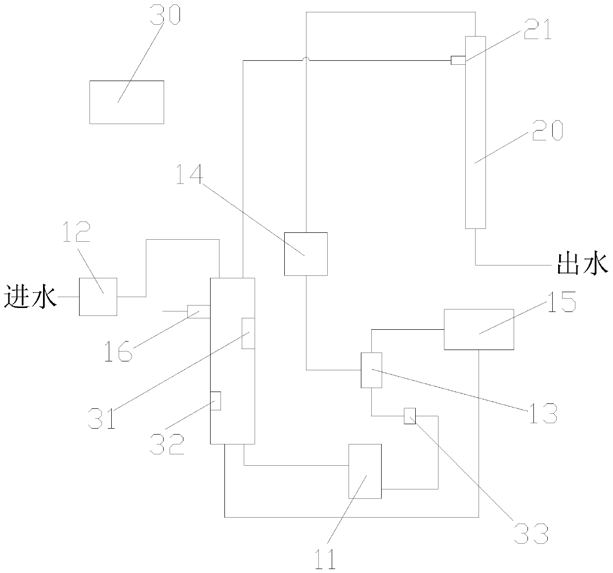
[0026] like figure 1 As shown, the present invention provides intestinal hydrotherapy equipment, comprising: a water tank 10, a circulating water pump 11 and a pressure pipe 20, the water outlet at the bottom of the water tank 10 is connected to the circulating water pump 11, and the water outlet of the circulating water pump 11 is connected to the pressure pipe 20 through a pipeline, The topmost height of the pressure pipe 20 is higher than that of the circulating water pump 11 and can be adjusted up and down. The standard pressure pipe 20 has a height of 1.6 meters, and the outlet pressure of the pressure pipe 20 is 10-12kPa.
[0027] Working principle of the present invention is:
[0028] In the intestinal hydrotherapy equipment provided by the present invention, because the water pump transports the liquid, the pressure instability is likely to occur. The height of the topmost part of the pressure pipe 20 is higher than the height of the circulating water pump 11 and can b...
Embodiment 2
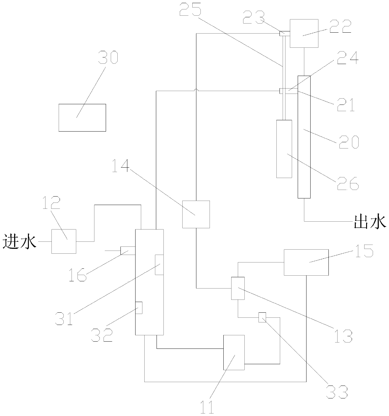
[0037] like figure 2 As shown, in order to enable the transfer box 22 and the pressure pipe 20 to be able to adjust the height, the preferred technical solution is that the transfer box 22 is located directly above the pressure pipe 20, and the side water inlet of the transfer box 22 is connected to the first horizontal pipe 23, and the first horizontal pipe The pipe 23 communicates with the water outlet of the circulating water pump 11 through a pipeline, and the first overflow port 21 on the side of the pressure pipe 20 is connected with the second horizontal pipe 24, and the second horizontal pipe 24 is connected with the top of the water tank 10 through a pipeline; A support rod 25 is connected between the pipe 23 and the second horizontal pipe 24, and a telescopic rod 26 is arranged directly below the support rod 25, and the telescopic end of the telescopic rod 26 is connected with the lower end of the support rod 25. The transfer box 22 and the pressure pipe 20 are move...
Embodiment 3
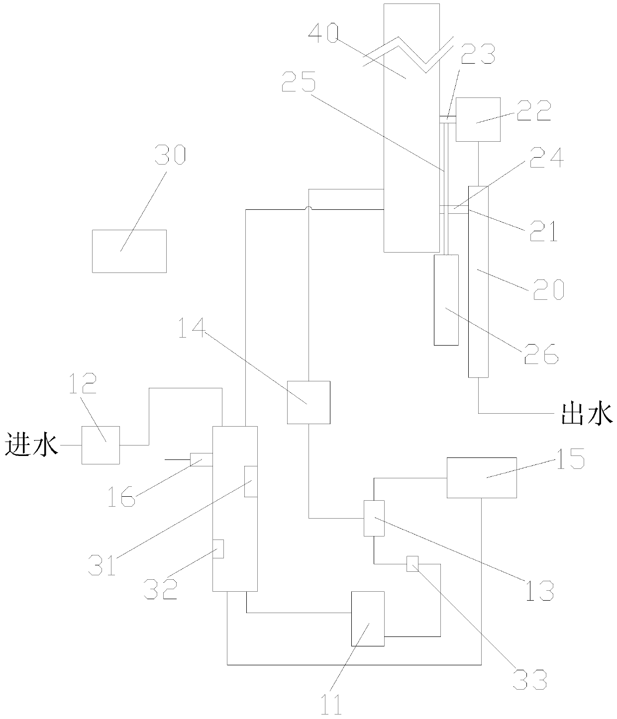
[0039] like image 3 , 4 , 5, in order to make the movement trajectory of the transfer box 22 and the pressure pipe 20 more stable, and at the same time prevent the pipeline connecting the water outlet of the circulating water pump 11 and the second overflow port 16 from being too chaotic, the preferred technical solution is that the first horizontal The ends of the pipe 23 and the second cross pipe 24 are equipped with sliders 27, and the first cross pipe 23 and the second cross pipe 24 pass through the sliders 27; The pipeline placement box 40 is provided with a vertical first slideway 41 corresponding to the sides of the first horizontal pipe 23 and the second horizontal pipe 24, and the slider 27 is arranged in the first slideway 41 and can slide up and down. The circulating water pump 11 The pipeline connecting the water outlet and the second overflow port 16 is a bendable pipe 17 , and the bendable pipe 17 is fixed on the side of the pipeline placement box 40 opposite t...
PUM
 Abstract
Description
Claims
Application Information
 - R&D
- Intellectual Property
- Life Sciences
- Materials
- Tech Scout
- Unparalleled Data Quality
- Higher Quality Content
- 60% Fewer Hallucinations
Browse by: Latest US Patents, China's latest patents, Technical Efficacy Thesaurus, Application Domain, Technology Topic, Popular Technical Reports.
© 2025 PatSnap. All rights reserved.Legal|Privacy policy|Modern Slavery Act Transparency Statement|Sitemap|About US| Contact US: help@patsnap.com


