Distributed efficient flotation machine

A flotation machine, distributed technology, applied in flotation, solid separation and other directions, can solve the problems of difficult to achieve the best state of flotation, inflexible flotation method, difficult closed-circuit flotation, etc., to achieve stable flotation effect, The effect of shortened flotation time and high flotation efficiency

Pending Publication Date: 2018-11-06
王益庆
View PDF0 Cites 1 Cited by
  • Summary
  • Abstract
  • Description
  • Claims
  • Application Information

AI Technical Summary

Problems solved by technology

[0004] The flotation method of the traditional flotation machine is inflexible. Due to the small amount of aeration and difficult regulation, not only the flotation efficiency is low, but also the necessary flexible regulation cannot be performed according to the flotation characteristics and processes of various minerals. Therefore, flotation is passive and difficult. To achieve the best state of flotation required by the process, some special processes such as: using low foam layer and high foam layer alternately, or high-speed flotation with a large amount of air, or maintaining flotation with a small amount of air, etc.
Traditional flotation equipment cannot meet these requirements, and there are more or less dead angles in stirring and flotation in traditional flotation equipment in the closed-circuit flotation process. Closed-circuit flotation becomes very difficult, and the process indicators caused by the equipment are missing. very obvious

Method used


Image

  • Distributed efficient flotation machine
  • Distributed efficient flotation machine
  • Distributed efficient flotation machine

Examples


Embodiment Construction

[0017] In order to make the object, technical solution and advantages of the present invention clearer, the present invention will be described in detail below in conjunction with the accompanying drawings and specific embodiments.

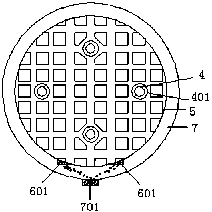
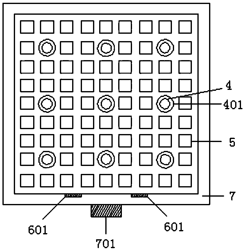
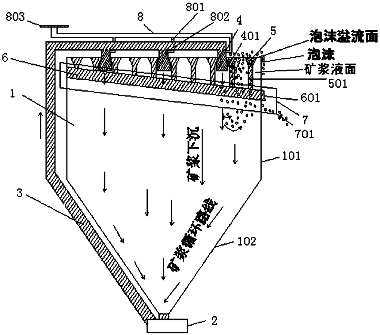
[0018] A distributed high-efficiency flotation machine, including a vertical cone barrel 1, a centrifugal wear-resistant slurry pump 2, a slurry PE conduit 3, a slurry nozzle 4, a foam collection cone trough 5, a foam collection main pipe in the barrel 6, and a Foam ring collection tank 7, gas main air pipe 8, described vertical vertebral barrel 1 is divided into upper barrel 101 and lower barrel 102, and described upper barrel 101 is an open cylinder (embodiment one, as figure 1 Shown) or square cylinder (embodiment two, such as figure 2 As shown), the lower bucket 102 is a corresponding conical cylinder or a square pyramid cylinder, and all the ore pulp runs from top to bottom without dead angle, and there is no area for the ore particles to se...


PUM


Abstract

The invention discloses a distributed efficient flotation machine. The distributed efficient flotation machine comprises a vertical tapered barrel (1), a centrifugal abrasion-resistant slag slurry pump (2), an ore pulp PE pipe (3), a plurality of ore pulp spray heads (4), a tapered foam collection tank (5), an intra-barrel foam collection main pipe (6), an annular extra-barrel foam collection tank(7) and an inflation main pipe (8). The vertical tapered barrel (1) is divided into an upper barrel body (101) and a lower barrel body (102), wherein the upper barrel body (101) is an open cylinder or a quadrangular square cylinder, and the lower barrel body (102) is a conical cylinder or a rectangular cylinder; and the bottom of the lower barrel body (102) is connected with the centrifugal abrasion-resistant slag slurry pump (2) and the ore pulp PE pipe (3), the ore pulp PE pipe (3) extends to a position above the top of the vertical tapered barrel (1) from bottom to top and is provided withthe ore pulp spray heads (4) which communicate with one another and face downwards, and the ore pulp spray heads (4) extend to the ore pulp level in the vertical tapered barrel (1).

Description

technical field [0001] The invention belongs to the field of mechanical equipment, and in particular relates to a distributed high-efficiency flotation machine. Background technique [0002] Due to the specific structure of the traditional flotation machine, a large part of the power is actually allocated to the weight of the rotor and the agitation of the pulp, and it is allocated to the insufficient power of aeration. There is too much power waste, which is not conducive to the original meaning of aeration flotation, and it is not energy-saving. Environmental protection increases the cost of beneficiation. [0003] The froth obtained by the traditional flotation machine is limited to one edge of the container, and the flotation column is limited to the edge of the bucket. These methods do not achieve the maximum froth obtained, which is also a manifestation of low flotation efficiency. [0004] The flotation method of the traditional flotation machine is inflexible. Due t...

Claims


Application Information

Patent Timeline
Patent Type & Authority Applications(China)
IPC IPC(8): B03D1/14B03D1/24
CPCB03D1/1462B03D1/1456B03D1/242
Inventor 王益庆
Owner 王益庆
Why Eureka
Try Eureka