Gear hobbing machining tool and gear hobbing machining method

A processing method and gear hobbing technology, which can be applied to metal processing equipment, gear tooth manufacturing devices, gear teeth, etc., can solve the problems of affecting processing accuracy and high cost of use, and achieve the advantages of increasing the contact area, facilitating disassembly and assembly, and saving costs. Effect

Pending Publication Date: 2018-11-06
BAZHONG YUXIANG MACHINERY MFG
View PDF3 Cites 1 Cited by
  • Summary
  • Abstract
  • Description
  • Claims
  • Application Information

AI Technical Summary

Problems solved by technology

[0006] The purpose of the present invention is to overcome the problem that the hobbing limit column of the existing gear hobbing tooling is in direct contact with the product to be processed, which causes wear and affects the machining accuracy, and when the amount of wear exceeds the allowable error, the tooling can only be scrapped and the use cost is high , providing a gear hobbing tool and a gear hobbing method. The gear hobbing tool uses an expansion sleeve to directly contact the processed product. During processing, the product will not directly cause wear to the base cylinder, and the expansion sleeve can be replaced directly after wear. , there is no need to scrap the entire base, saving costs and ensuring processing accuracy. The expansion hole design of the expansion sleeve provides a certain reaction force and buffer force, which is suitable for the installation and processing of processed products, and better meets the use requirements and processing accuracy.

Method used


Image

  • Gear hobbing machining tool and gear hobbing machining method
  • Gear hobbing machining tool and gear hobbing machining method
  • Gear hobbing machining tool and gear hobbing machining method

Examples


Embodiment 1

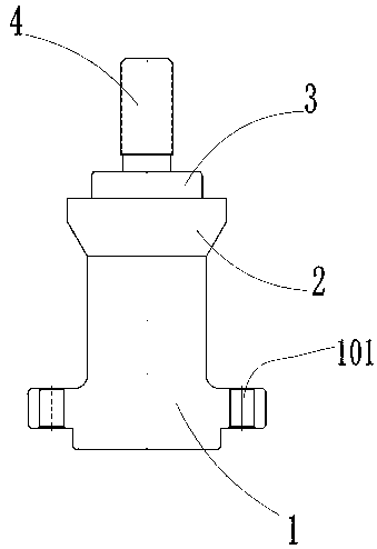
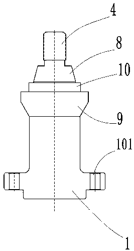
[0035] Such as Figure 1 to Figure 6 As shown, the gear hobbing tooling of this embodiment includes a columnar structure base 1 and an expansion sleeve 12 provided with the base 1, the expansion sleeve 12 is used to be sleeved on the cylinder of the base 1, and the base 1 It includes a section of expansion sleeve installation column 8 corresponding to the design of expansion sleeve 12. The contact surface of the expansion sleeve installation column 8 and expansion sleeve 12 is a conical surface that cooperates with each other. Multiple expansion holes 1201 are provided on the expansion sleeve 12. The outer ring surface of the expansion sleeve 12 is the tooth mounting surface corresponding to the processed product 5 .

[0036] The gear hobbing tooling of this embodiment is specially designed with the expansion sleeve installation column and the expansion sleeve. The expansion sleeve is directly in contact with the processed product. During processing, the product will not direc...

Embodiment 2

[0043] Such as Figure 1 to Figure 6 As shown, according to the gear hobbing tool described in Embodiment 1, the expansion hole 1201 of this embodiment includes a round hole penetrating through the wall of the expansion sleeve 12, and also includes a through groove communicating with the round hole, and the through groove extends to the expansion sleeve. 12 end faces. The design of the round hole of the expansion hole and the through groove extending to the end face of the expansion sleeve makes the wall of the expansion sleeve have a certain degree of expansion and cushioning, which is conducive to the firm combination of the expansion sleeve and the installation column of the expansion sleeve to ensure the stability of the installation of the processed product.

[0044] Further, the expansion sleeve 12 is provided with through grooves extending in two directions, respectively extending to the two end surfaces of the expansion sleeve 12 . The expansion sleeves are respective...

Embodiment 3

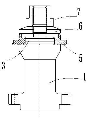
[0046] This embodiment provides a gear hobbing method. When the gear hobbing tool described in Embodiment 1 or Embodiment 2 is used for gear hobbing, the base 1 is first installed on the gear hobbing machine tool, and then the positioning plate 11 Install it on the positioning plate mounting platform 9 of the base 1 cylinder, then set the expansion sleeve 12 on the expansion sleeve installation column 8, and use the expansion hole 1201 to expand the expansion sleeve 12 to closely contact with the expansion sleeve installation column 8, and then install The processed product 5 and the lock nut 7 are hobbed by a gear hobbing machine tool.

[0047] In the gear hobbing processing method of this embodiment, by setting the expansion sleeve installation column and the expansion sleeve on the base cylinder, the processed product directly contacts with the expansion sleeve and does not directly contact the base cylinder, which avoids direct wear on the base cylinder and is convenient. ...


PUM


Abstract

The invention discloses a vehicle part machining technology. The gear hobbing machining tool, comprises a base and an expansion sleeve which is matched with the base, wherein the expansion sleeve is used for sleeving a column body of the base, the base comprises a section of expansion sleeve mounting column which is correspondingly designed with the expansion sleeve; the contact surfaces of the expansion sleeve mounting column and the expansion sleeve are conical surfaces cooperating with each other, a plurality of expansion holes are formed in the expansion sleeve, and the outer ring surfaceof the expansion sleeve is a gear tooth mounting surface corresponding to a machined product. The expansion sleeve used in the gear hobbing machining tool is in direct contact with the machined product, so that the product cannot be directly worn on a base column body in a machining process, the expansion sleeve can be directly replaced after being worn, the whole base does not need to be scrapped, so that the cost is saved, and the machining precision is guaranteed; the desigh of the expansion holes of the expansion sleeve provides a certain counter force and buffering force, and is suitablefor installation and machining of the machined product, so that use requirements and the machining precision are better met.

Description

technical field [0001] The invention relates to a processing technology for vehicle parts, in particular to a hobbing tooling and a gear hobbing method. Background technique [0002] Gear hobbing is a common transmission part for motorcycles, automobiles, etc. As the most common transmission and wear parts, hobbing gears are used in a huge amount, so how to process high-quality hobbing gears efficiently is more important. [0003] Such as figure 1 with figure 2 As shown, the existing gear hobbing tooling includes a columnar base 1, and a hobbing installation platform 2 is arranged on the upper part of the base 1. The hobbing installation platform 2 is connected with a hobbing limit column 3, and It is connected with a lock stud 4 for installing a lock nut. After the product 5 to be processed is installed on the hobbing installation table 2, the top is covered tightly with a gland 6 and the entire installation structure is locked with a lock nut 7. It is used to perform g...

Claims


Application Information

Patent Timeline
Patent Type & Authority Applications(China)
IPC IPC(8): B23F23/06B23F5/20
CPCB23F5/20B23F23/06
Inventor 王曾强
Owner BAZHONG YUXIANG MACHINERY MFG
Why Eureka
Try Eureka