Unlock instant, AI-driven research and patent intelligence for your innovation.

Strip welding mechanism

A welding mechanism and strip technology, applied in welding equipment, auxiliary welding equipment, welding/cutting auxiliary equipment, etc., can solve problems such as difficult welding operations, heavy coil materials, and insufficient continuity, so as to reduce manual participation and improve production efficiency effect

Active Publication Date: 2018-11-06
ANHUI XUANTONG IND DESIGN CO LTD
View PDF8 Cites 6 Cited by
  • Summary
  • Abstract
  • Description
  • Claims
  • Application Information

AI Technical Summary

Problems solved by technology

When the above-mentioned metal profiles are actually used, they need to be shut down, which leads to insufficient continuity during the production of metal profile snakes, and when the above-mentioned coils are spliced ​​and welded, because the coils are relatively heavy, the welding operation is more difficult and requires more Multiple operators participate at the same time, which is time-consuming and labor-intensive

Method used


Image

  • Strip welding mechanism
  • Strip welding mechanism
  • Strip welding mechanism

Examples


Embodiment Construction

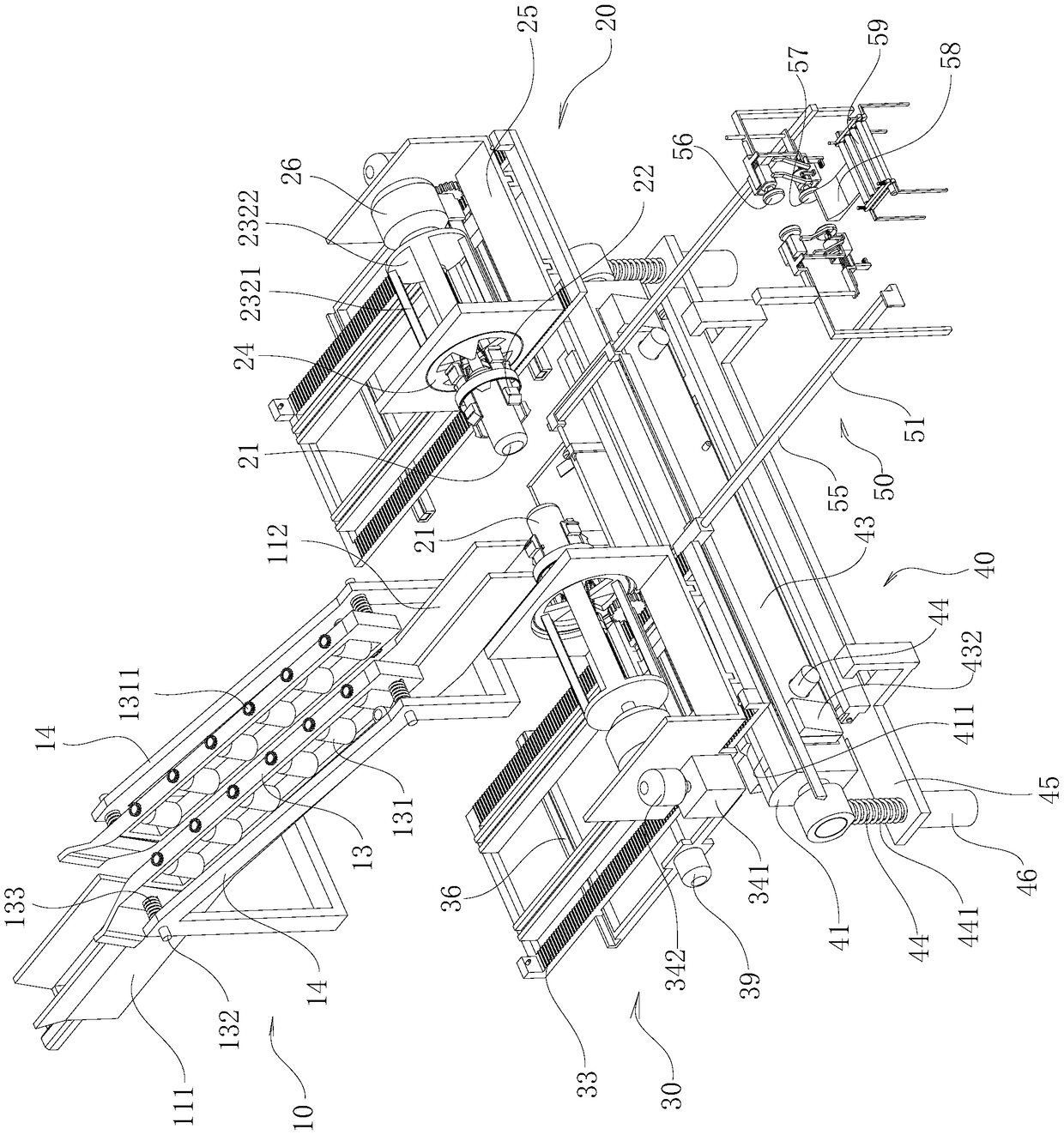
[0022] combine Figure 1 to Figure 21 , the present invention is further described:

[0023] In order to make the objects and advantages of the present invention clearer, the present invention will be described in detail below in conjunction with the examples. It should be understood that the following words are only used to describe one or several specific implementation modes of the present invention, and do not strictly limit the protection scope of the specific claims of the present invention.

[0024] As used herein, the terms "parallel" and "perpendicular" are not limited to their strict geometric definitions, but include reasonable and inconsistent tolerances for machining or human error.

[0025] Below in conjunction with the whole metal profile production system, the strip welding mechanism of the present invention is described in detail:

[0026] The specific features of this metal profile production system are described in detail below:

[0027] The metal profile...


PUM


Abstract

The invention relates to a strip welding mechanism. The strip welding mechanism comprises a first welding pressing plate and a second welding pressing plate which are arranged below the two sides of aknife plate of a cutting mechanism. A first vertical groove plate and a second vertical groove plate are arranged on a cushion block, a first welding pressing plate is slidingly arranged in the firstvertical groove plate, a second welding pressing plate is slidingly arranged in the second vertical groove plate, a first extension support is arranged on the first welding pressing plate and the second welding pressing plate, a second cross plate is arranged on a second extension support, a guide column vertically penetrates through a first cross plate to be connected with the lower plate face of the cushion block, the guide column is sleeved with a second supporting spring, the upper end and the lower end of the second supporting spring abut against the first cross plate and the second cross plate, an iron core rod is arranged on the lower plate face of the first cross plate, the iron core rod is vertically downward and stretches out of the lower plate face of the second cross plate, asecond electromagnetic coil is arranged on the second cross plate, and the lower end of the iron core rod is sleeved with the second electromagnetic coil. The strip welding mechanism can adapt to continuous production of profiles, artificial participation is reduced, and the production efficiency of the profiles is improved.

Description

technical field [0001] The invention relates to the technical field of profile production, in particular to a strip welding mechanism. Background technique [0002] Metal profiles are widely used in the field of building materials. In the actual production of metal profiles, the coils need to be unloaded first. The strips exported from the coils are bent by a bending machine to form profiles with required cross-sections. The anti-oxidation film is pasted on the profile to reduce the corrosion and oxidation of the profile. During the actual production of the above-mentioned metal profile coil, when a single coil of steel plate is almost used up, it is necessary to use a new coil and a nearly exhausted coil. Coil splicing, specifically aligning the end of the previously used coil with the first end of the coil to be used, and welding the two coils together by welding equipment, in order to achieve continuous continuous bending production of profiles , the head ends of the abo...

Claims


Application Information

Patent Timeline
IPC IPC(8): B23K37/00B23K37/02B23K37/04B23P23/00
CPCB23K37/00B23K37/0211B23K37/0443B23P23/00
Inventor 陈建业
Owner ANHUI XUANTONG IND DESIGN CO LTD