
Cradle rotary table dragged by ball screw

A ball screw and turntable technology, applied in the field of cradle turntable, can solve the problems of large rotating shaft end size, mechanical turntable wear, tooth surface adhesion, etc., to improve transmission efficiency, reduce shaft end size, and save space. Effect

Active Publication Date: 2018-11-06
KEDE NUMERICAL CONTROL CO LTD
View PDF5 Cites 8 Cited by
  • Summary
  • Abstract
  • Description
  • Claims
  • Application Information

AI Technical Summary

Problems solved by technology

[0004] The mechanical turntable has problems such as wear, heat, and tooth surface adhesion; the torque motor turntable has problems such as small torque, high cost, and large size of the rotating shaft end

Method used


Image

  • Cradle rotary table dragged by ball screw
  • Cradle rotary table dragged by ball screw
  • Cradle rotary table dragged by ball screw

Examples


Embodiment Construction

[0034] In order to make the purpose, technical solutions and advantages of the embodiments of the present invention clearer, the technical solutions in the embodiments of the present invention will be clearly and completely described below in conjunction with the drawings in the embodiments of the present invention. Obviously, the described embodiments It is a part of embodiments of the present invention, but not all embodiments. Based on the embodiments of the present invention, all other embodiments obtained by persons of ordinary skill in the art without creative efforts fall within the protection scope of the present invention.

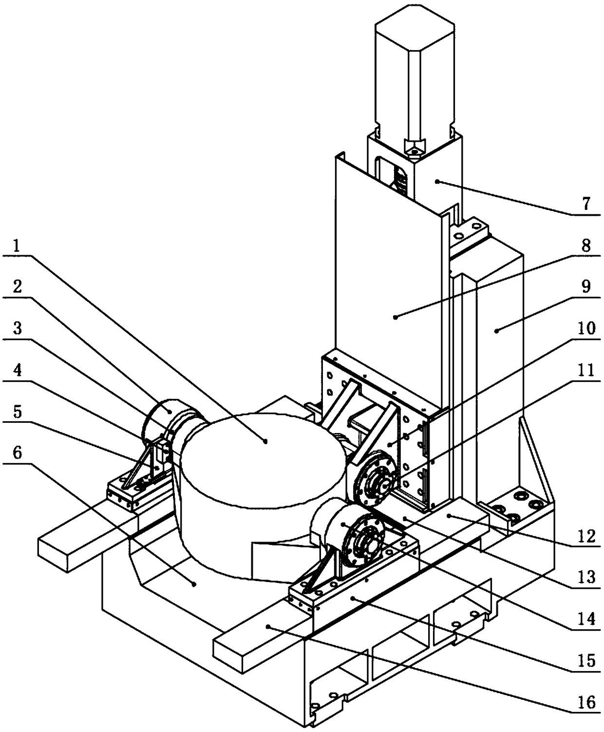
[0035] figure 1 It is a structural schematic diagram of the cradle turntable dragged by the ball screw of the present invention, as figure 1 As shown, the cradle turntable structure of the present embodiment may include:

[0036] a turntable, a base, a column perpendicular to the base, a first swing mechanism, a second swing mechanism, a third s...


PUM


Abstract

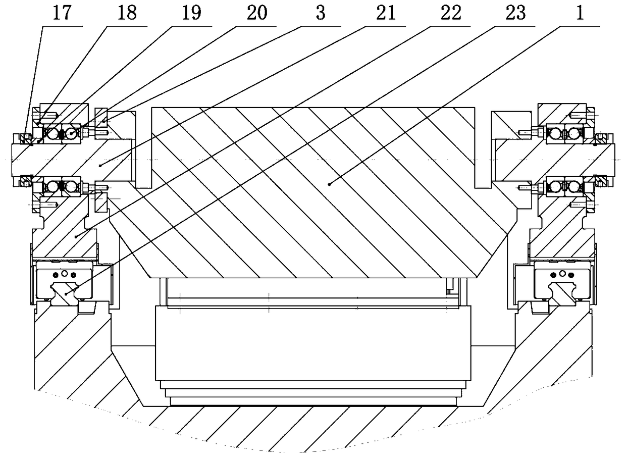
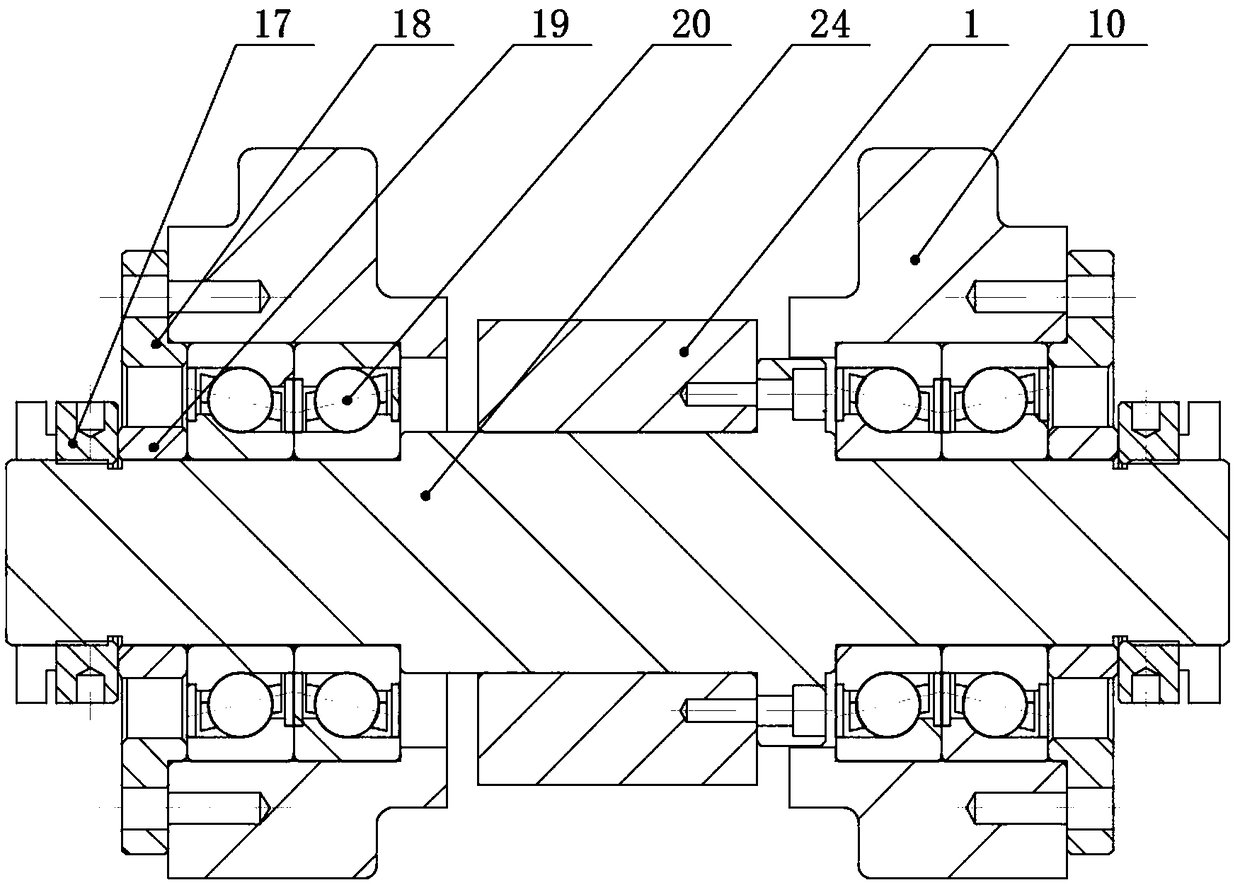
The invention discloses a cradle rotary table dragged by a ball screw. The cradle rotary table dragged by the ball screw comprises a rotary table body, a base and a stand column perpendicular to the base, and further comprises a first swing mechanism, a second swing mechanism, a third swing mechanism and a dragging mechanism; the first swing mechanism and the second swing mechanism which are fixedto the base are arranged at the two ends of the rotary table body separately; the third swing mechanism is connected with a boss structure at the rear end of the rotary table body; and the dragging structure is arranged on the stand column and drives the third swing mechanism to move on the stand column. The cradle rotary table dragged by the ball screw does not generate the conditions of tooth surface abrasion, heating expansion and tooth surface adhesion, improves the transmission efficiency, enlarges the torque, reduces the cost, reduces the shaft end size and saves the space.

Description

technical field [0001] The invention relates to the technical field of metal processing, in particular to a cradle turntable driven by a ball screw. Background technique [0002] In recent years, with the development of the manufacturing industry, the demand for machining centers is also increasing. Among them, the five-axis linkage machining center can greatly improve production efficiency, and can process some parts with high surface requirements, which is suitable for processing high-precision parts with complex surfaces. [0003] There are many ways to realize the five-axis. Whether it is a vertical or a horizontal machining center, it mainly uses 3+2 or 3+1+1 to realize the five-axis linkage. The X, Y, and Z axes are the three axes of the machine tool. The basic axis, the other two axes are realized with the spindle head or rotary table. The two-axis CNC turntable is a more commonly used method. This kind of turntable has mechanical (worm gear or gear) transmission an...

Claims


Application Information

Patent Timeline
Patent Type & Authority Applications(China)
IPC IPC(8): B23Q1/44B23Q11/08
CPCB23Q1/44B23Q11/08B23Q1/5462
Inventor 陈虎侯延星段惠强范春宏张传思李秀敏王阔赵立新
Owner KEDE NUMERICAL CONTROL CO LTD
Learn More