
Milling tool with multifunctional blade compensation

A multi-functional, blade technology, applied in the direction of manufacturing tools, other manufacturing equipment/tools, metal processing equipment, etc., can solve the problems of high production scrap rate, non-compliance with requirements, large workpiece errors, etc., and achieve convenient operation, easy maintenance and Maintenance, stable effect of processing

Inactive Publication Date: 2018-11-06
邓聪迪
View PDF0 Cites 1 Cited by
  • Summary
  • Abstract
  • Description
  • Claims
  • Application Information

AI Technical Summary

Problems solved by technology

[0002] With the development of science and technology and the progress of society, the country has been promoting the development of high technology. In the field of machining technology, there has always been a relatively difficult technical problem. In machining, there are often certain milling errors in cutting tools. Due to the general There is no compensation for the blade of the equipment tool, resulting in a large error in the processed workpiece, which does not meet the requirements, and the production scrap rate is high. This device effectively solves this problem

Method used


Image

  • Milling tool with multifunctional blade compensation
  • Milling tool with multifunctional blade compensation

Examples


Embodiment Construction

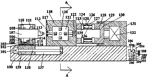
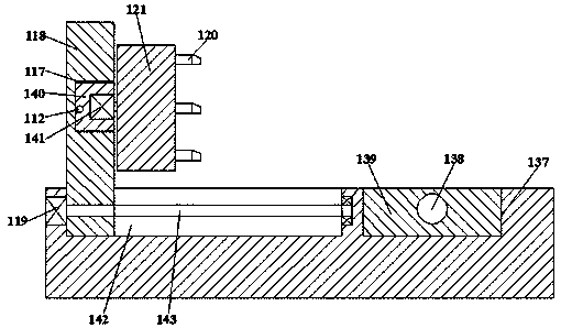
[0014] Such as figure 1 with figure 2 As shown, the milling tool with multi-function blade compensation of the present invention includes a machine tool 100 and a power machine body 131 arranged on the top end of the machine tool 100. The left end of the power machine body 131 is provided with a circular groove 129 opening to the left. , The circular groove 129 is rotatably connected with a fixing sleeve 130 extending left and right, the left end of the fixing sleeve 130 extends out of the circular groove 129, and the fixing sleeve 130 is provided with a fixing hole with a leftward opening 128. A first motor 132 is dynamically connected to the right end surface of the firmware sleeve 130. The outer surface of the first motor 132 is embedded in the inner wall of the right end of the circular groove 129 and is fixedly connected to it. A left-right symmetrical groove 123 is connected to the inner wall. An annular groove 136 is provided between the two grooves 123. The top of the ...


PUM


Abstract

The invention discloses a milling tool with multifunctional blade compensation. The milling tool comprises a machine tool, and a power machine body arranged on the top end face of the machine tool; the left end face of the power machine body is internally provided with a circular groove with an opening leftward; the interior of the circular groove is connected to a firmware sleeve in a running fitmanner, and the firmware sleeve extends right and left; the left end of the firmware sleeve extends out of the circular groove; the firmware sleeve is internally provided with a firmware hole with anopening leftward, and the right end face of the firmware sleeve is in power connection with a first motor of which the outside surface is embedded in and fixedly connected to the inner wall of the right end of the circular groove; the circumferential inner wall of the firmware hole is provided with bilaterally symmetrical grooves in a communicating manner, and a ring groove is arranged between the two grooves in the communicating manner; and the top of the ring groove is provided with a first cavity in the communicating manner. The milling tool has the advantages of the simple structure, easyoperation, convenient fixation and chambering, and stable machining.

Description

Technical field [0001] The invention relates to the technical field of machining, in particular to a milling tool with multifunctional blade compensation. Background technique [0002] With the development of science and technology and the progress of society, the country has always promoted the development of high technology. In the field of machining technology, there has always been a more difficult technical problem. There are often some milling errors in the cutting tools in machining. There is no compensation for the blade of the equipment tool, which results in a large error in the processed workpiece, which does not meet the requirements, and the production scrap rate is high. This device effectively solves this problem. Summary of the invention [0003] The technical problem to be solved by the present invention is to provide a milling tool with multi-function blade compensation, which can solve the above-mentioned problems in the current technology. [0004] The present i...

Claims


Application Information

Patent Timeline
Patent Type & Authority Applications(China)
IPC IPC(8): B23Q3/06B23Q5/28B23Q23/00
CPCB23Q3/06B23Q5/28B23Q23/00
Inventor 邓聪迪
Owner 邓聪迪
Learn More