
Adjustable fixture based on blade root inclined surface positioning

A fixture and bevel technology, applied in the field of debuggable fixtures, can solve the problems of low positioning accuracy, shorten the calibration fixture time, poor versatility, etc., and achieve the effects of ensuring stability and accuracy, improving service life, and improving general performance.

Active Publication Date: 2018-11-06
JIANGSU UNIV
View PDF8 Cites 7 Cited by
  • Summary
  • Abstract
  • Description
  • Claims
  • Application Information

AI Technical Summary

Problems solved by technology

[0005] The invention provides an adjustable fixture device aimed at the positioning of blade root slopes, which is easy to operate and easy to use, which can solve the problems of poor versatility and low positioning accuracy of the existing steam turbine blade processing tooling, and is suitable for various blade root forms and installations. Angled blades can not only ensure the processing quality requirements of the workpiece, improve labor productivity, but also save fixture manufacturing materials and production costs, and shorten the time for fixture calibration

Method used


Image

  • Adjustable fixture based on blade root inclined surface positioning
  • Adjustable fixture based on blade root inclined surface positioning
  • Adjustable fixture based on blade root inclined surface positioning

Examples


Embodiment Construction

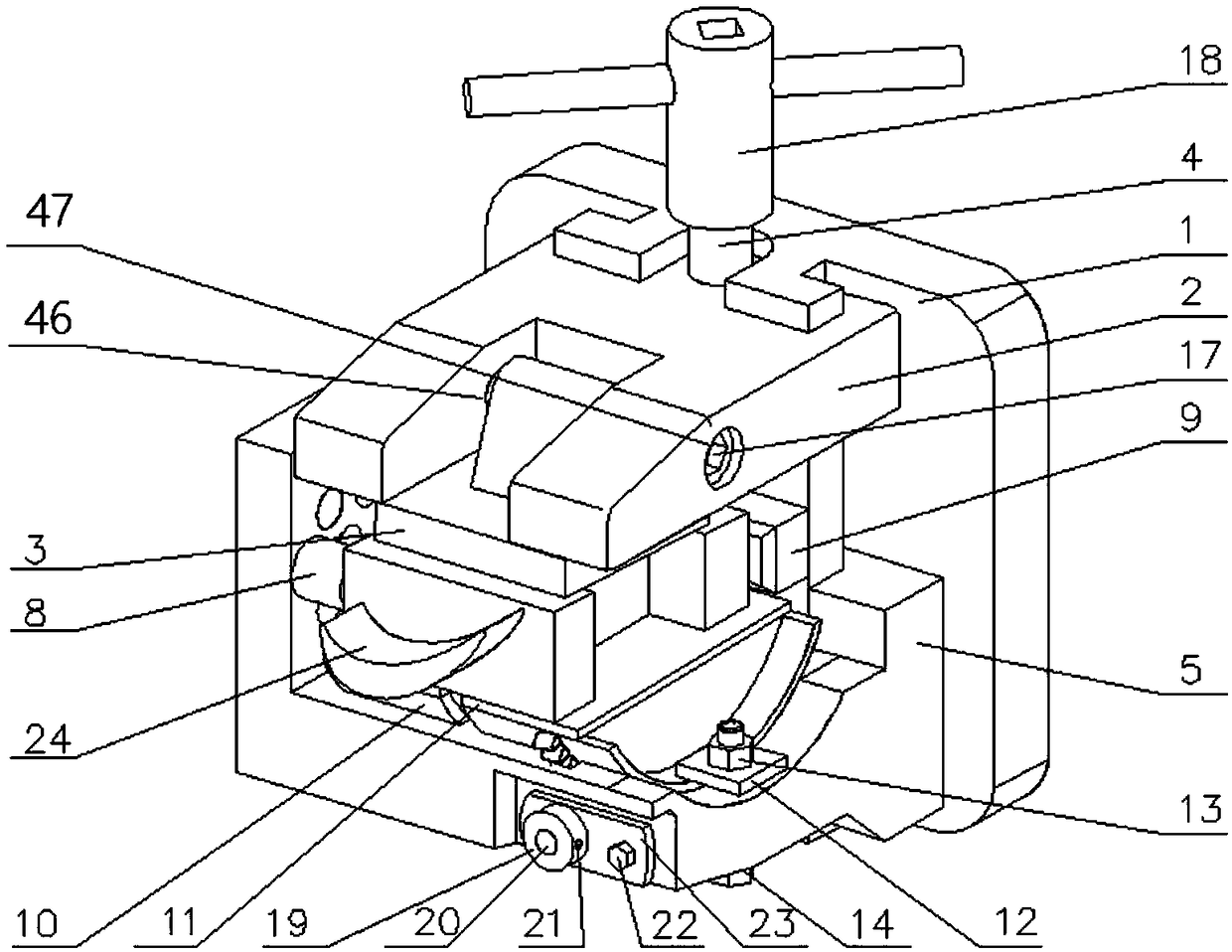
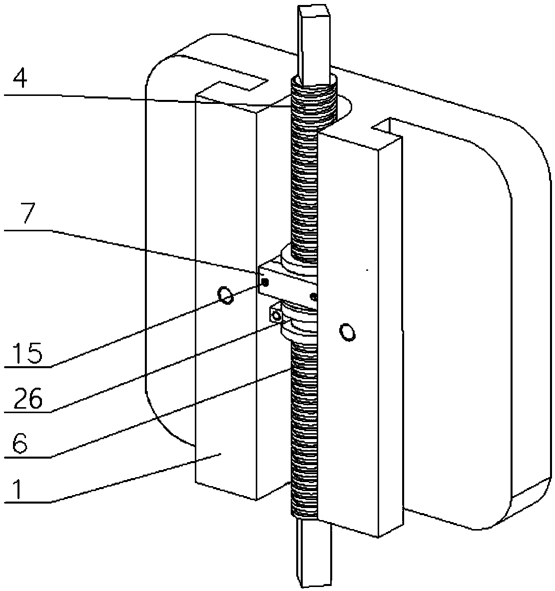
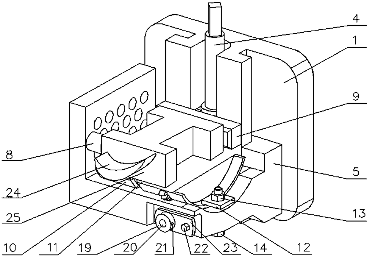
[0035] An adjustable fixture based on blade root slope positioning, including clamp body 1, movable upper cover 2, clamping plate 3, upper cover screw 4, movable positioning platform 5, positioning platform screw 6, screw fixing plate 7, and positioning support nails 8. Positioning support plate 9, angle adjustment block 10, positioning plane plate 11, pressure plate 12, compression nut 13, compression bolt 14, fixing screw 15, countersunk screw 16, clamping plate shaft 17, screw handle 18, angle Adjustment handle 19, angle adjustment rod 20, self-locking screw 21, hexagon bolt 22, fixed sleeve 23. The clamp body 1 is connected to the main shaft of the machine tool.

[0036]The upper cover screw 4 and the positioning table screw 6 are respectively installed in the upper and lower screw installation cavities of the clamp body 1 through two screw fixing plates 7 . The positioning table screw rod 6 is threadedly connected with the movable positioning table 5, and the movable pos...


PUM


Abstract

The invention relates to the field of tool fixtures for steam turbine blade machining, in particular to an adjustable fixture based on blade root inclined surface positioning. The fixture uses a bladeroot radial surface as a main positioning surface; a blade root tail part is positioned by adopting a positioning support plate; and a blade root molded surface is positioned by a replaceable positioning support nail mounted on a movable positioning table. The fixture comprises a fixture body, a movable upper cover, a clamping plate, the movable positioning table, an angle adjusting block, a positioning plane plate, an angle adjusting rod and the like. The movable positioning table is provided with a chute matched with the fixture body for shifting the movable positioning table up and down toadapt to different blade root thicknesses. A positioning support nail is mounted at the left end of the movable positioning table; and an angle adjusting block is mounted in an arc groove. Before clamping, the angle adjusting rod is rotated to adjust the inclined angle of the angle adjusting block; and the positioning support nail with proper length is replaced to guarantee consistency of the blade root center and the fixture revolving center after clamping. The clamping of blades is realized through buckling and pressing of a clamping plate by an upper cover. The clamping of different typesof blades is met; and the blade machining efficiency is improved.

Description

technical field [0001] The invention relates to the field of tooling fixtures for processing steam turbine blades, in particular to an adjustable fixture based on blade root inclined plane positioning, which is suitable for clamping and positioning of blades with different blade root forms and blade root sizes. Background technique [0002] As the core part of the steam turbine blade, its processing quality and efficiency play an important role in the safety and economy of the steam turbine unit. A large part of the processing quality depends on the accuracy and stability of the fixture. [0003] The traditional fixture processes the blade profile, blade crown, etc. by positioning the blade root and tenon teeth. It is easy to damage the blade root profile during the clamping process, and when the radial surface is used as the positioning plane, the method of adding gaskets is usually used to meet the positioning requirements. It is inconvenient to adjust, it cannot be reus...

Claims


Application Information

Patent Timeline
Patent Type & Authority Applications(China)
IPC IPC(8): B23Q3/12
CPCB23Q3/12B23Q2703/10
Inventor 鲁金忠杜家龙邵亦锴罗开玉
Owner JIANGSU UNIV
Learn More