Load platform for rock mechanical testing

A technology of rock mechanics and loading, applied in the field of rock mechanics testing, can solve the problems of mechanical damage of precision cable, high operation risk, load sensor damage, etc., to achieve the effect of preventing falling damage, supporting stable and strong, and avoiding damage

Pending Publication Date: 2018-11-06
SICHUAN UNIV
View PDF6 Cites 2 Cited by
  • Summary
  • Abstract
  • Description
  • Claims
  • Application Information

AI Technical Summary

Problems solved by technology

The existing method is manual operation. Even if many people cooperate, it is difficult to disassemble and install the high-temperature and high-pressure load sensor with large mass in the narrow high-temperature and high-pressure pressure chamber. In addition, the load sensor accidentally falls under improper disassembly and assembly, which may cause serious damage to the load sensor. Physical damage may cause mechanical damage to many precision cables on the high temperature and high pressure base, and may even cause serious personal injury to the installer
Manual operation is extremely difficult and risky. The fundamental reason is that manual lifting power and lifting time are limited, and manual lifting is easy to shake and has poor stability.
But for a major difficulty and pain point in rock mechanics testing in the deep environment
At present, there is no effective solution and equipment for this problem

Method used


Image

  • Load platform for rock mechanical testing
  • Load platform for rock mechanical testing
  • Load platform for rock mechanical testing

Examples


Embodiment Construction

[0019] Below in conjunction with accompanying drawing and embodiment the present invention is described further as follows:

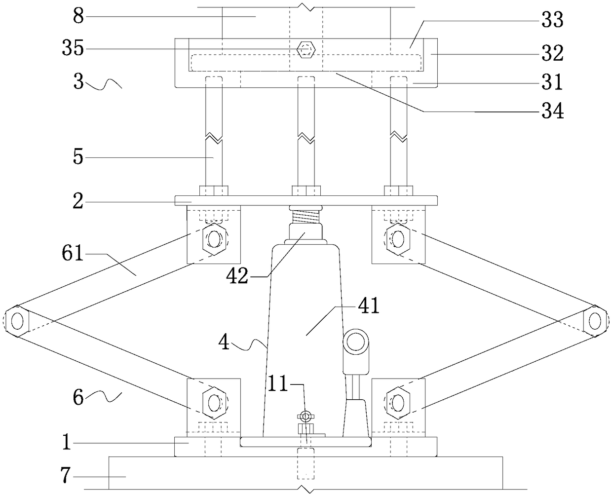
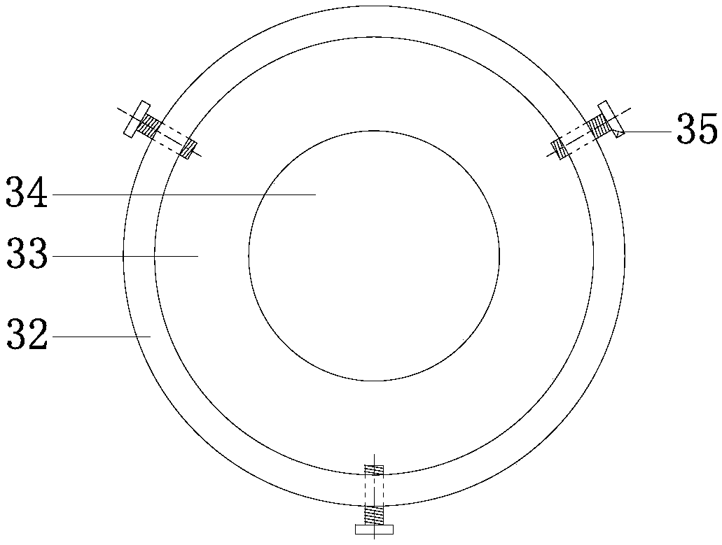
[0020] like figure 1 As shown, a load platform for rock mechanics testing includes a base 1, a lifting seat 3, and an intermediate connection seat 2 between the base 1 and the lifting seat 3; Assembly 4; the piston end of the hydraulic assembly 4 is connected to the bottom of the intermediate connecting seat 2, and the other end is connected to the base 1; the intermediate connecting seat 2 and the lifting seat 3 are connected through a set of connecting rods 5 The holding seat 3 includes a base plate 31 and a side wall 32 arranged on the base plate 31; surrounded by the side wall 32 and the base plate 31 to form an upward accommodating groove 33 for accommodating the MTS high temperature and high pressure sensor; The center of the bottom plate 31 of the lifting seat 3 is provided with an operation channel 34 passing through the bottom plate 31 along i...


PUM


Abstract

The invention is a load platform for rock mechanical testing, and belongs to the field of rock mechanical testing. The load platform aims to improve the stability and reliability of lifting. The loadplatform comprises a base, a lifting seat and a middle connecting seat between the base and the lifting seat; a hydraulic assembly is arranged between the base and the middle connecting seat, and themiddle connecting seat is connected with the lifting seat through a set of connecting rods; the lifting seat is surrounded by a side wall and a bottom plate to form an accommodating groove with an upward opening; and a limiting device for preventing an MTS triaxial force sensor from separating from a supporting plate is disposed on the side wall of the lifting seat. A bearing device replaces the human support to carry out the disassembly and assembly of the force sensor, and time and effort are saved; the bearing for the force sensor is more stable and powerful, the force sensor can be appliedwith a certain pulling force, and the difficulty of the force sensor being difficult to disassemble in the presence of the oil suction force can be effectively overcome; lifting is achieved by the hydraulic assembly, and the lifting is stable; and a reliable limiting structure can effectively prevent the force sensor from falling and being damaged in case of accident.

Description

technical field [0001] The invention belongs to the field of rock mechanics testing of engineering rock mass, and is used for solving the disassembly, alignment and safety problems of high-temperature and high-pressure load sensors in the existing Mechanics Test System (MTS) test system. Background technique [0002] Deep engineering rock mass is in a complex stress state and environment such as high temperature, high pressure, high seepage flow and dynamic load. Deep engineering construction needs to first know the mechanical properties of engineering rock mass in the deep complex environment, which is necessary for engineering construction and safe operation. Provide basis and basic data. The MTS rock mechanics testing machine produced by MTS Corporation of the United States is currently one of the most advanced and widely used rock mechanics equipment in the world, which can simulate the rock mechanics response under complex conditions at a certain depth. In order to ens...

Claims


Application Information

Patent Timeline
Patent Type & Authority Applications(China)
IPC IPC(8): B66F7/08B66F7/28G01N3/02
CPCG01N3/02B66F7/0641B66F7/08B66F7/28G01N33/24G01N3/18G01N2203/0048G01N2203/0256G01N2203/0226G01N2203/0232G01L5/0028G01N3/06G01N3/10G01N2203/0676G01N2203/0694
Inventor 刘建锋李志成曾寅王春萍雷孝章符文熹
Owner SICHUAN UNIV
Why Eureka
Try Eureka