Method for treating cyanobacteria
A treatment method, cyanobacteria technology, applied in water/sewage treatment, chemical instruments and methods, water treatment under pressure conditions, etc., can solve problems such as inability to form turbulent flow
- Summary
- Abstract
- Description
- Claims
- Application Information
AI Technical Summary
Problems solved by technology
Method used
Image
Examples
Embodiment 1
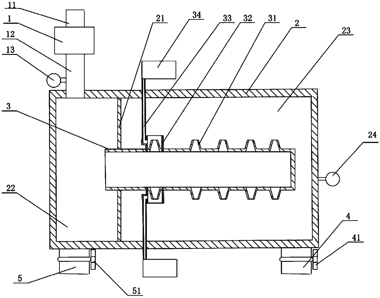
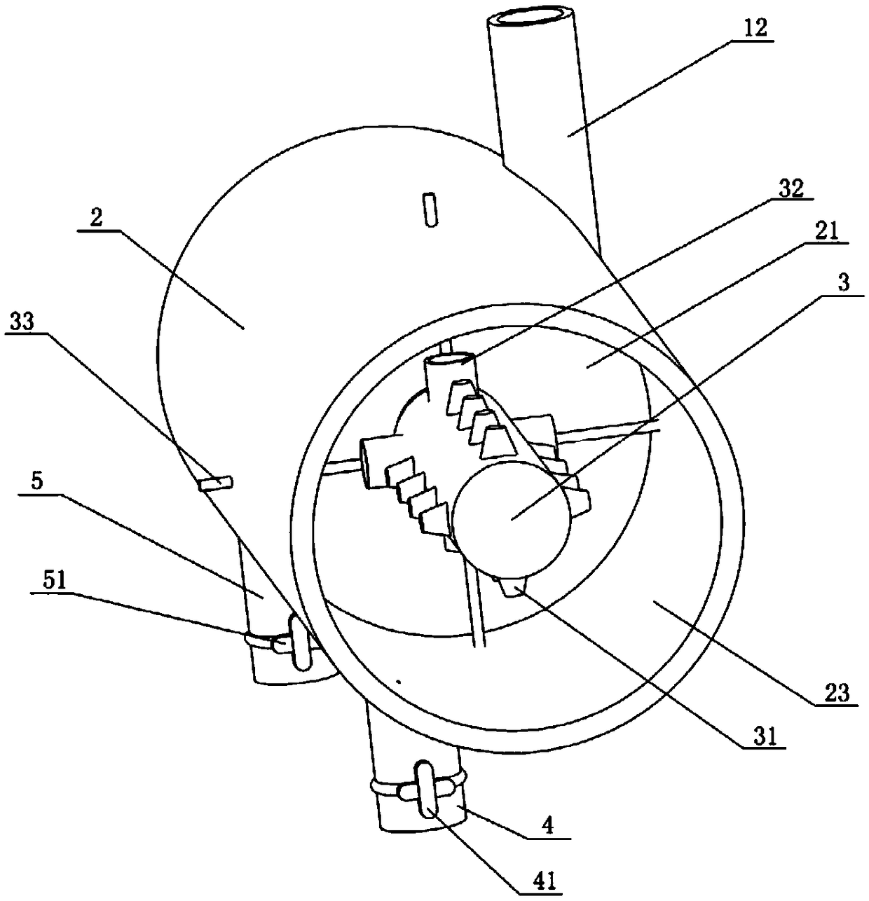
[0066] See figure 1 , figure 2 , a method for treating cyanobacteria, comprising the following steps,
[0067] pressurization; the liquid containing cyanobacteria is sent into the first airtight container 2, and the liquid is pressurized to 0.2-10MPa;
[0068] Turbulent flow; make the liquid continue to spray on the inner surface of the first airtight container 2 to form a turbulent flow until the liquid flow rate reaches 1.5-25m / s;
[0069] Introduce air; the liquid remains turbulent in the first airtight container 2, and the air is introduced into the first airtight container 2 until it is evenly mixed with the liquid, and the pressure value in the first airtight container 2 is kept between 0.1MPa-10MPa .
[0070] Before the pressurizing step, the following steps are also included,
[0071] To determine whether the cyanobacteria contained in the liquid are poisonous:
[0072] If so, then when introducing the air step, regulate and control the pressure value in the firs...
Embodiment 2
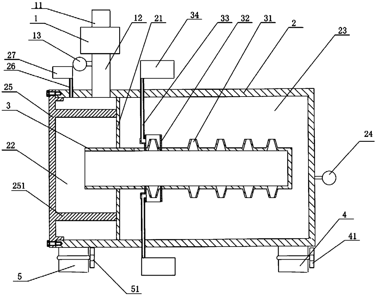
[0095] See image 3 , Figure 4, wherein, the booster pump 1 is provided with a suction pipe 11 and a liquid outlet pipe 12 communicating with the left chamber 22, the first airtight container 2 also includes a left end cover 25, the left end cover 25 is arranged on the left end of the left chamber 22 and can The left chamber 22 is sealed, and the left end cover 25 is protruded with at least two deflectors 251 spaced apart from the inner wall of the first airtight container 2. The deflectors 251 form a circular array with the axis of the left end cover 25 as the front. Distribution, wherein a deflector 251 is arranged below the liquid outlet pipe 12 and is inclined toward the liquid outlet pipe 12 . One end of the deflector 251 is fixedly connected to the left end cover 25 , and the other end is against the partition plate 21 . It also includes a vent pipe 26 and an air storage chamber 27 , the vent pipe 26 runs through the outer wall of the left chamber 22 , and one end is ...
Embodiment 3
[0102] See Figure 5 , Figure 6 , Figure 7 , Figure 8 , a detoxification step comprising the following steps,
[0103] Make the flow velocity of the liquid to 0.1-1.5m / s;
[0104] The liquid to be processed is introduced into the second airtight container 6;
[0105] The ultraviolet lamp 8 that is located in the second airtight container 6 is irradiated,
[0106] At the same time, ozone is introduced into the second airtight container.
[0107] The remaining parts are the same as in Embodiment 1 or Embodiment 2.
[0108] Wherein, the ozone introduced can be the ozone stored in the storage room, or the ozone converted from oxygen by setting an ozone generator. To make the flow velocity of the liquid to 0.1-1.5m / s, the following technical means can be used. Through the pipeline velocimeter 612, the flow rate of the liquid is monitored in real time and converted into an electrical signal to feed back to the solenoid valve 611. The solenoid valve 611 automatically adjus...
PUM
 Abstract
Description
Claims
Application Information
 - R&D
- Intellectual Property
- Life Sciences
- Materials
- Tech Scout
- Unparalleled Data Quality
- Higher Quality Content
- 60% Fewer Hallucinations
Browse by: Latest US Patents, China's latest patents, Technical Efficacy Thesaurus, Application Domain, Technology Topic, Popular Technical Reports.
© 2025 PatSnap. All rights reserved.Legal|Privacy policy|Modern Slavery Act Transparency Statement|Sitemap|About US| Contact US: help@patsnap.com


