A kind of yarn expanding method and equipment
An expansion method and a technology for expansion equipment, applied in the field of yarn expansion methods and equipment, can solve the problems of many strand dyeing processes, low production efficiency, uneven dyeing, etc.
- Summary
- Abstract
- Description
- Claims
- Application Information
AI Technical Summary
Problems solved by technology
Method used
Image
Examples
Embodiment 1
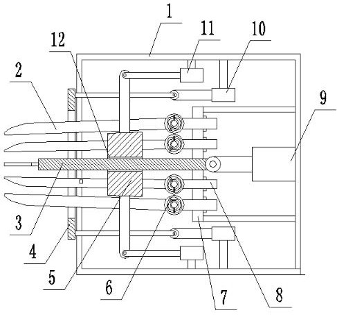
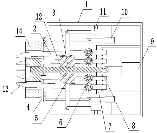
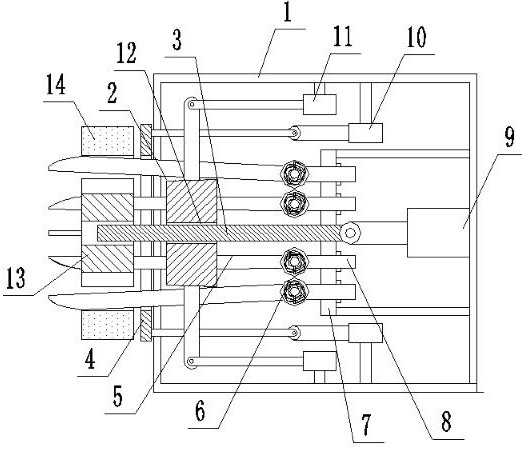
[0042] like Figures 1 to 10 As shown, a yarn extension method, the following steps:
[0043] a, winding the yarn coil 14 on the loose bobbin 13;
[0044] b, insert the positioning rod 3 into the guide hole 12 on the loose tube 13;
[0045] c, inserting a plurality of inserts 2 into the evenly distributed gaps 15 on the loose bobbin tube 13;
[0046] d, expand the inserting body 2 inserted into the gap 15 outward, spread the yarn coil 14 along the outer circle direction of the yarn coil 14, make the yarn coil 14 separate from the loose bobbin 13, and take away the loose bobbin 13;
[0047] e, put the net cylinder 17 on the positioning rod 3;
[0048] f, the insert body 2 shrinks inwardly along the inner diameter direction of the mesh cylinder 17, and restores to its original shape, and the yarn coil 14 shrinks inwardly;
[0049] g, the insertion body 2 moves in one direction to break away from the yarn coil 14, and the push plate 4 moves in the opposite direction to push t...
Embodiment 2
[0053] like Figures 1 to 10 As shown, a yarn extension method, the following steps:
[0054] a, winding the yarn coil 14 on the loose bobbin 13;
[0055] b, insert the positioning rod 3 into the guide hole 12 on the loose tube 13;
[0056] c, inserting a plurality of inserts 2 into the evenly distributed gaps 15 on the loose bobbin tube 13;
[0057] d, expand the inserting body 2 inserted into the gap 15 outward, spread the yarn coil 14 along the outer circle direction of the yarn coil 14, make the yarn coil 14 separate from the loose bobbin 13, and take away the loose bobbin 13;
[0058] e, put the net cylinder 17 on the positioning rod 3;
[0059] f, the insert body 2 shrinks inwardly along the inner diameter direction of the mesh cylinder 17, and restores to its original shape, and the yarn coil 14 shrinks inwardly;
[0060] g, the insertion body 2 moves in one direction to break away from the yarn coil 14, and the push plate 4 moves in the opposite direction to push t...
Embodiment 3
[0068] like Figures 1 to 10 As shown, a yarn extension method, the following steps:
[0069] a, winding the yarn coil 14 on the loose bobbin 13;
[0070] b, insert the positioning rod 3 into the guide hole 12 on the loose tube 13;
[0071] c, inserting a plurality of inserts 2 into the evenly distributed gaps 15 on the loose bobbin tube 13;
[0072] d, expand the inserting body 2 inserted into the gap 15 outward, spread the yarn coil 14 along the outer circle direction of the yarn coil 14, make the yarn coil 14 separate from the loose bobbin 13, and take away the loose bobbin 13;
[0073] e, put the net cylinder 17 on the positioning rod 3;
[0074] f, the insert body 2 shrinks inwardly along the inner diameter direction of the mesh cylinder 17, and restores to its original shape, and the yarn coil 14 shrinks inwardly;
[0075] g, the insertion body 2 moves in one direction to break away from the yarn coil 14, and the push plate 4 moves in the opposite direction to push t...
PUM
| Property | Measurement | Unit |
|---|---|---|
| diameter | aaaaa | aaaaa |
Abstract
Description
Claims
Application Information
 - R&D
- Intellectual Property
- Life Sciences
- Materials
- Tech Scout
- Unparalleled Data Quality
- Higher Quality Content
- 60% Fewer Hallucinations
Browse by: Latest US Patents, China's latest patents, Technical Efficacy Thesaurus, Application Domain, Technology Topic, Popular Technical Reports.
© 2025 PatSnap. All rights reserved.Legal|Privacy policy|Modern Slavery Act Transparency Statement|Sitemap|About US| Contact US: help@patsnap.com


