
Power generation device using residual potential energy

A power generation device and potential energy technology, applied in the direction of engines, machines/engines, boreholes/well components, etc., can solve the problems of wind power generation failure, potential energy conversion into kinetic energy loss, etc., to achieve strong practicability, novel design, and good working conditions require simple effects

Pending Publication Date: 2018-11-06
赵建明
View PDF12 Cites 1 Cited by
  • Summary
  • Abstract
  • Description
  • Claims
  • Application Information

AI Technical Summary

Problems solved by technology

Nowadays, fossil fuels are mostly used for power generation, but the resources of fossil fuels are not many and are becoming increasingly exhausted. Human beings have gradually used more renewable energy sources (water energy, solar energy, wind energy, geothermal energy, ocean energy, etc.) to generate electricity. At present, there are Wind power generation and solar power generation have disadvantages. When there is no wind, wind power generation cannot generate electricity, and when there is no sun and rainy days, solar energy cannot generate electricity. The beam pumping unit can generate potential energy during work. And then converted into kinetic energy, however, the potential energy is partially lost in the process of converting into kinetic energy

Method used


Image

  • Power generation device using residual potential energy
  • Power generation device using residual potential energy
  • Power generation device using residual potential energy

Examples


Embodiment Construction

[0018] The following will clearly and completely describe the technical solutions in the embodiments of the present invention with reference to the accompanying drawings in the embodiments of the present invention. Obviously, the described embodiments are only some, not all, embodiments of the present invention. Based on the embodiments of the present invention, all other embodiments obtained by persons of ordinary skill in the art without making creative efforts belong to the protection scope of the present invention.

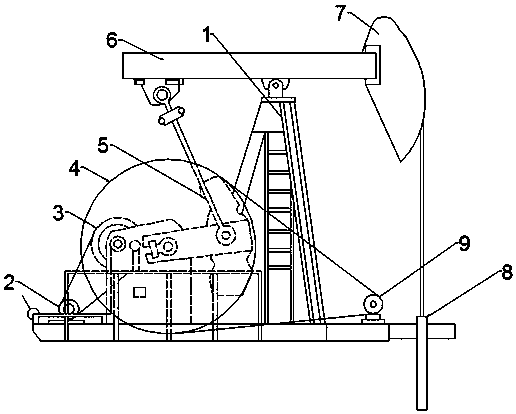
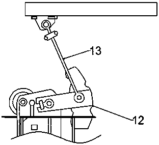
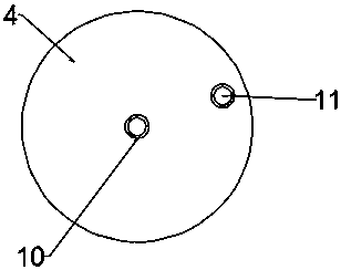
[0019] see Figure 1~3 , in an embodiment of the present invention, a power generation device utilizing residual potential energy includes a bracket 1, a motor 2, a driven wheel 4, a crank mechanism 5 and a generator 9; the crank mechanism 5 is installed on the bracket 1, and the crank mechanism 5 includes Rotate connecting rod 12 and swing connecting rod 13, the right end of rotating connecting rod 12 is rotationally connected with an end of swinging connecti...


PUM


Abstract

The invention discloses a power generation device using residual potential energy. The power generation device comprises a bracket, a driven wheel, a crank mechanism and a power generator. The crank mechanism is mounted on the bracket. The driven wheel is arranged at the front end of the crank mechanism. A driven wheel circle center shaft is fixedly mounted at the circle center position of the driven wheel. A driven wheel eccentric shaft is fixedly mounted at the eccentric position of the driven wheel. The driven wheel is rotationally connected with a belt wheel at the front end of an output shaft of the power generator through a transmission belt. The power generation device is novel in design, electric energy of an oil pumping unit is converted into mechanical energy through a motor matched with a beam-pumping unit, lifting potential energy is converted into free-fall motion through the weight of an underground oil pumping rod underground the oil pumping unit in the downstroke process of the beam-pumping unit, part of the potential energy is further converted into kinetic energy due to the action of a balance block, the potential energy of down-stroke underground oil pumping is greater than part of the converted kinetic energy, the residual potential energy means that the unconverted potential energy is converted into electrical energy, and thus collection and conversion of the energy are achieved.

Description

technical field [0001] The invention relates to a power generating device, in particular to a power generating device utilizing residual potential energy. Background technique [0002] Beam pumping unit, also known as beam pumping unit and beam pumping unit with crank balance, refers to a pumping unit that contains a beam, reverses direction through a connecting rod mechanism, and balances crank weights, commonly known as a kowtow machine. In terms of oil production methods, it is rod-type oil production equipment (from the perspective of oil production methods, it can be divided into two categories, namely, rod-type oil production equipment and rod-free oil production equipment). [0003] Power generation refers to the conversion of water energy, thermal energy of fossil fuels (coal, oil, natural gas, etc.), nuclear energy, solar energy, wind energy, geothermal energy, ocean energy, etc. into electricity by means of a power generation unit. Nowadays, fossil fuels are mostl...

Claims


Application Information

Patent Timeline
Patent Type & Authority Applications(China)
IPC IPC(8): E21B43/00F03G3/00
CPCE21B43/12F03G3/00
Inventor 赵建明
Owner 赵建明
Learn More