Fast cooling device for hydraulic device

A technology of cooling device and hydraulic device, which is applied to fluid pressure actuating device, fluid pressure actuating system components, servo meter circuit, etc. speed, avoid the effect of oil viscosity change

Inactive Publication Date: 2018-11-06
HUAIAN SHENGJIE HYDRAULIC MACHINERY
View PDF0 Cites 3 Cited by
  • Summary
  • Abstract
  • Description
  • Claims
  • Application Information

AI Technical Summary

Problems solved by technology

[0005] Aiming at the deficiencies of the prior art, the present invention provides a rapid cooling device for hydraulic devices, which has the advantages of improving th

Method used


Image

  • Fast cooling device for hydraulic device
  • Fast cooling device for hydraulic device

Examples


Example Embodiment

[0019] The technical solutions in the embodiments of the present invention will be clearly and completely described below in conjunction with the accompanying drawings in the embodiments of the present invention. Obviously, the described embodiments are only a part of the embodiments of the present invention, rather than all the embodiments. Based on the embodiments of the present invention, all other embodiments obtained by those of ordinary skill in the art without creative work shall fall within the protection scope of the present invention.

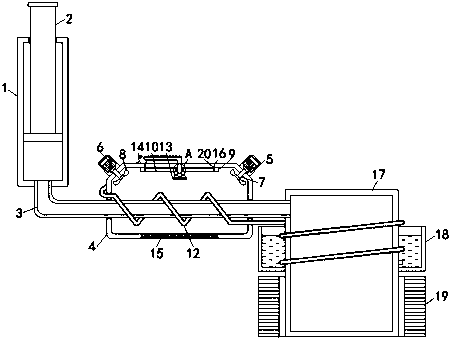
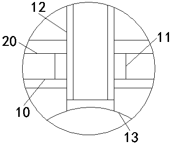
[0020] See Figure 1-2 , The present invention provides a technical solution: a quick cooling device for a hydraulic device, comprising a cylinder barrel 1, a piston rod 2 is movably connected to the inside of the cylinder barrel 1, and an oil return pipe 3 is fixedly connected to the bottom of the cylinder barrel 1. A cooling box 4 is fixedly connected to the outside of 3, two chassis 5 are fixedly installed on the top of the cooling bo...


PUM


Abstract

The invention relates to the technical field of hydraulic device cooling and discloses a fast cooling device for a hydraulic device. The fast cooling device comprises a cylinder barrel. A piston rod is movably connected in the cylinder barrel. An oil return pipe is fixedly connected to the bottom of the cylinder barrel. The outer side of the oil return pipe is fixedly connected with a cooling box.Two cases are fixedly installed on the top of the cooling box. A motor is fixedly installed in each case. An output shaft of each motor is fixedly connected with a rotating shaft. The bottom end of each rotating shaft is fixedly connected with a fan blade. A sliding plate is fixedly installed on the inner top wall of the cooling box. A sliding groove is formed in the bottom of the sliding plate.A sliding block is connected in the sliding groove in a sliding manner. According to the fast cooling device for the hydraulic device, the cooling effect of the hydraulic cooling device is improved greatly, the cooling speed is effectively increased, the change of oil viscosity due to change of the oil temperature is avoided, thus the situation that transmission efficiency becomes bad is avoided,and normal work of a machine can be ensured.

Description

technical field [0001] The invention relates to the technical field of hydraulic device cooling, in particular to a rapid cooling device for hydraulic devices. Background technique [0002] Hydraulic equipment is the carrier of the hydraulic system. A complete hydraulic system consists of five parts, namely power components, actuators, control components, auxiliary components and hydraulic oil. Hydraulic equipment is the combination of various parts. The transmission force of hydraulic equipment is large. Easy to transmit and configure, widely used in industrial and civil industries, the function of the hydraulic cylinder and hydraulic motor is to convert the pressure energy of the liquid into mechanical energy, and obtain the required linear reciprocating motion or rotary motion, which can be customized according to the needs Design actions, modify components at will to achieve the desired work. [0003] There are still some deficiencies in the existing cooling devices for...

Claims


Application Information

Patent Timeline
IPC IPC(8): F15B21/04
CPCF15B21/042F15B2211/62
Inventor 田守港
Owner HUAIAN SHENGJIE HYDRAULIC MACHINERY
Why Eureka
Try Eureka