Vehicle vibration energy recovery type shock absorber

A vibration energy recovery and shock absorber technology, applied in the direction of shock absorbers, liquid shock absorbers, shock absorbers, etc., can solve the problems of limited frame space, high cost, low power generation efficiency, etc., and achieve high energy utilization , The effect of small energy loss and extreme energy loss

Active Publication Date: 2018-11-06
金湖县综合检验检测中心
View PDF8 Cites 1 Cited by
  • Summary
  • Abstract
  • Description
  • Claims
  • Application Information

AI Technical Summary

Problems solved by technology

However, in the actual use of this patent, it is found that because it requires an additional motion conversion mechanism, not only the cost is relatively high, but also because the vane motor realizes forward and reverse rotation according to the flow direction of the oil in the cylinder to drive the generator to rotate and generate electricity, so When the flow direction of the oil changes, its force on the vane motor needs to overcome the rotational inertia of the previous vane motor, and then the remaining energy can re-drive the vane motor to rotate to generate electricity; in fact, the energy of the oil in the flow process is first consumed After overcoming the vane motor in the original motion state, it can generate electricity, and its power generation efficiency is very low; in addition, in the actual assembly process of the vehicle, it was also found that the frame space of the vehicle is relatively limited, and the existence of the motion conversion mechanism requires the motion conversion mechanism Leaving enough space will inevitably lead to shortening of the stroke of the piston in the cylinder or other structural changes, which will cause additional burden on the design of auto parts

Method used


Image

  • Vehicle vibration energy recovery type shock absorber
  • Vehicle vibration energy recovery type shock absorber
  • Vehicle vibration energy recovery type shock absorber

Examples


Embodiment Construction

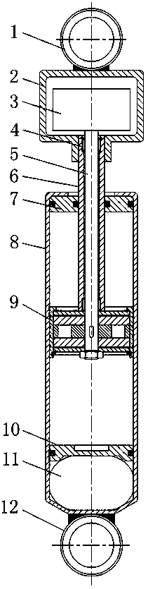
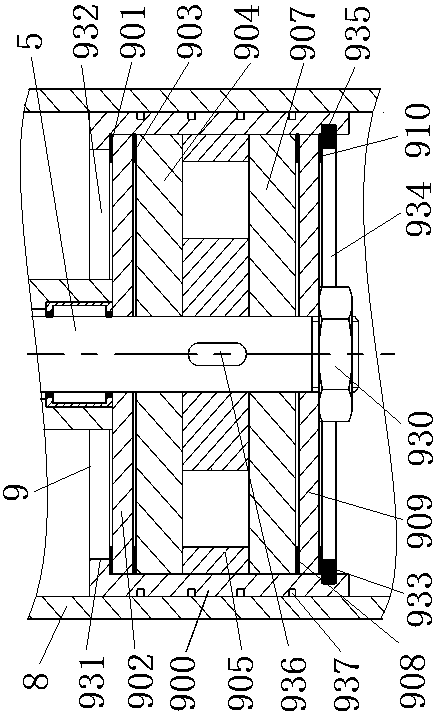
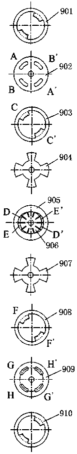
[0040] combine Figure 1~Figure 12 It can be seen that the vehicle vibration energy recovery type shock absorber of the present invention includes a cylinder 8 and a piston 9 matched with the cylinder 8, the end of the piston rod 6 of the piston 9 protrudes from the cylinder 8 and is fixed with the generator 3 , the piston rod 6 is a hollow tube, and the coaxial rotation of the piston rod 6 is connected with an output shaft 5. One end of the output shaft 5 is connected to the main shaft of the generator 3, and the other end is connected to the piston 9. The piston 9 includes a tubular casing 900, which is provided with an annular diaphragm spring A901, an upper valve seat 902, an annular diaphragm spring B903, an upper side plate 904, a vane motor, and a lower side in sequence from top to bottom. Plate 907, annular diaphragm spring C908, lower valve seat 909 and annular diaphragm spring D910, the rotor 906 of the vane motor is fixed to the output shaft 5, and the end of the ge...


PUM


Abstract

The invention discloses a vehicle vibration energy recovery type shock absorber comprising a cylinder barrel and a piston matched with the cylinder barrel. The end of a piston rod of the piston extends out of the cylinder barrel, and fixed to a generator; the piston rod is a hollow pipe, and the interior of the piston rod is rotatably connected to an output shaft coaxially; one end of the output shaft is in transmission connection with a main shaft of the generator, and the other end of the output shaft is connected to the piston; the piston comprises a tubular shell which is provided with a ring diaphragm spring A, an upper valve seat, a ring diaphragm spring B, an upper side plate, a blade motor, a lower side plate, a ring diaphragm spring C, a lower valve seat and a ring diaphragm spring D from top to bottom in sequence; and a rotor of the blade motor is fixed to the output shaft. From the above structure, according to the vehicle vibration energy recovery type shock absorber, through the special structure of the piston, the application directions of oil in the cylinder barrel to the rotor of the blade motor are consistent regardless of upward or downward movement of the pistonrelative to the cylinder barrel.

Description

technical field [0001] The invention relates to the technical field of a built-in vane motor type energy recovery shock absorber, in particular to a vehicle vibration energy recovery type shock absorber. Background technique [0002] At present, the shock absorbers used in automobiles are generally passive shock absorbers. When the suspension reciprocates relative to the vehicle body, the piston in the shock absorber also reciprocates relative to the cylinder, forcing the hydraulic oil in the cylinder to pass through an oil chamber. The narrow gaps on the piston flow into another oil chamber. The friction between these gaps and the oil and the internal friction of the liquid molecules form a damping force against vibration, which converts the energy generated by the vibration of the car into the heat energy of the oil and dissipates it into the atmosphere. To achieve the purpose of damping vibration. If this part of energy can be effectively recycled, it can reduce the ener...

Claims


Application Information

Patent Timeline
Patent Type & Authority Applications(China)
IPC IPC(8): F16F9/19F16F9/32F16F9/34F16F9/36
CPCF16F9/19F16F9/3207F16F9/34F16F9/36
Inventor 胡晓明管倡华戴建国陈勇
Owner 金湖县综合检验检测中心
Why Eureka
Try Eureka