Semiconductor refrigeration dehumidifier and dehumidification method thereof

A semiconductor and dehumidifier technology, applied in refrigerators, refrigeration and liquefaction, machine operation and other directions, can solve problems such as low energy efficiency, low failure rate and low service life, improve heat exchange efficiency, reduce flow pressure loss, simplify The effect of structural design

Pending Publication Date: 2018-11-06
AUX AIR CONDITIONING LTD BY SHARE LTD
View PDF7 Cites 8 Cited by
  • Summary
  • Abstract
  • Description
  • Claims
  • Application Information

AI Technical Summary

Problems solved by technology

[0002] The core component of the semiconductor refrigeration dehumidifier is the "semiconductor refrigeration sheet", which has two sides. After power on, one side absorbs heat and cools, which is the "cold side", and the other side releases heat as the "hot side". The air flows through the "cold side" first. , the moisture in the air is removed by cooling and condensing, and the cooled air flows through the "hot surface" to cool the "hot surface" of the cooling sheet. Because of its small size, simple structure, low failure rate, and long service life, it is widely used. application, but limited by the conditions of the semiconductor refrigeration sheet itself, it has the disadvantage of low energy efficiency compared with vapor compression refrigeration and dehumidification

Method used


Image

  • Semiconductor refrigeration dehumidifier and dehumidification method thereof
  • Semiconductor refrigeration dehumidifier and dehumidification method thereof
  • Semiconductor refrigeration dehumidifier and dehumidification method thereof

Examples


Embodiment 1

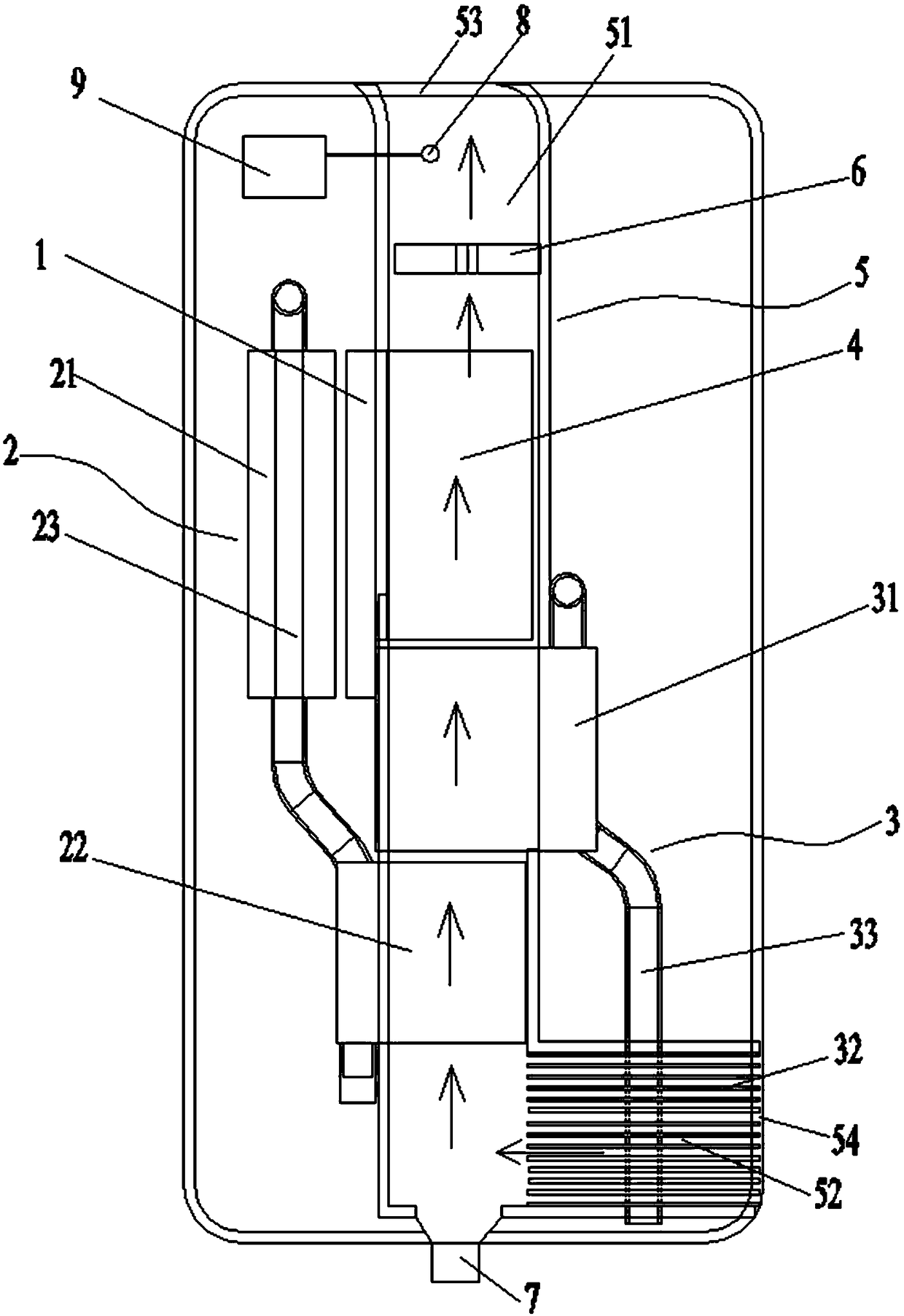
[0042] Such as figure 1 As shown, it is a schematic structural diagram of a semiconductor refrigeration dehumidifier provided in this embodiment, and the dehumidifier includes:

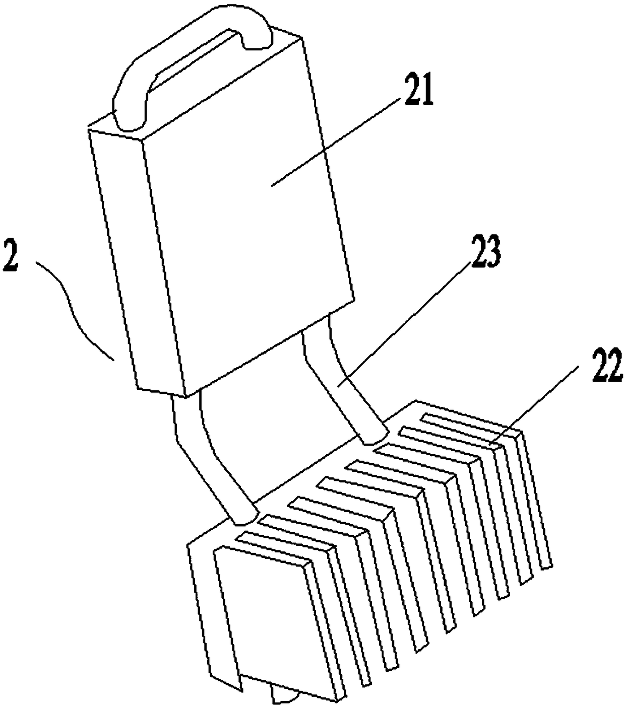
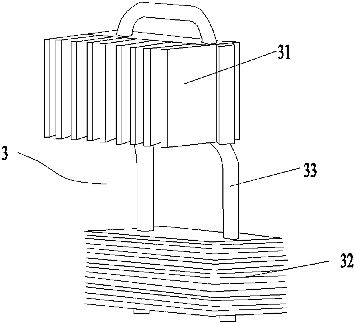
[0043] Semiconductor cooling chip 1, first heat transfer device 2, second heat transfer device 3, third heat transfer device 4, air duct 5, exhaust fan 6, water outlet 7;

[0044] The air passage 5 includes an air outlet 51 and an air inlet 52; the outlet of the air outlet 51 is provided with an air outlet 53, and the exhaust fan 6 is located at the air outlet 53; the air inlet The entrance of 52 is provided with an air inlet 54;

[0045] One end of the second heat transfer device 3 is located in the air inlet channel 52, pre-cools the air entering from the air inlet 54, and transfers the absorbed air heat to the other part of the second heat transfer device 3. one end;

[0046] One end of the first heat transfer device 2 is located in the air outlet channel 51 to secondary cool the pre-cooled air;...

Embodiment 2

[0059] Such as figure 1 As shown, it is a schematic structural diagram of a semiconductor refrigeration dehumidifier provided in this embodiment. The difference between this embodiment and the above embodiment is that a humidity sensor 8 is also provided at the air outlet 53 of the air outlet duct 51; A controller 9 is also arranged outside the air outlet 51; the controller 9 is electrically connected with the humidity sensor 8, the semiconductor refrigeration sheet 1 and the exhaust fan 6, receives the humidity data detected by the humidity sensor 8, and passes the humidity data at the air outlet 53 Analyze and control the operation of semiconductor refrigeration sheet 1 and exhaust fan 6.

[0060] The setting of the humidity sensor 3 and the controller facilitates real-time monitoring of the dehumidification effect of the dehumidifier.

[0061] The dehumidification method of the above-mentioned semiconductor refrigeration dehumidifier comprises the following steps:

[0062...


PUM


Abstract

The invention provides a double-heat-pipe semiconductor refrigeration dehumidifier and a dehumidification method of the double-heat-pipe semiconductor refrigeration dehumidifier. The double-heat-pipesemiconductor refrigeration dehumidifier comprises a semiconductor refrigeration sheet, a first heat transfer device, a second heat transfer device, a third heat transfer device, an air flue, an exhaust fan and a water outlet. Heat exchange and dehumidification of air are performed through the arrangement of the three heat transfer devices, and the first heat transfer device can transfer the cooling capacity of the cold face of the semiconductor refrigeration sheet and performs secondary cooling on the air in an air-discharging channel through the absorbed cooling capacity of the cold face ofthe semiconductor refrigeration sheet. The third heat transfer device can transfer the heat of the hot face of the semiconductor refrigeration sheet and performs secondary heating on the air in the air-discharging channel, the air passes through the cold face for heat exchange in advance and then passes through the hot face for heat exchange without changing the direction, structural design of theair flue is simplified, the flowing pressure loss of the air in the air flue is reduced, and the dehumidification efficiency of the whole dehumidifier is improved.

Description

technical field [0001] The invention relates to the technical field of dehumidifiers, in particular to a semiconductor refrigeration dehumidifier and a dehumidification method thereof. Background technique [0002] The core component of the semiconductor refrigeration dehumidifier is the "semiconductor refrigeration sheet", which has two sides. After power on, one side absorbs heat and cools, which is the "cold side", and the other side releases heat as the "hot side". The air flows through the "cold side" first. , the moisture in the air is removed by cooling and condensing, and the cooled air flows through the "hot surface" to cool the "hot surface" of the cooling sheet. Because of its small size, simple structure, low failure rate, and long service life, it is widely used. However, it is restricted by the conditions of the semiconductor refrigeration chip itself, which makes it have the disadvantage of low energy efficiency compared with vapor compression refrigeration an...

Claims


Application Information

Patent Timeline
Patent Type & Authority Applications(China)
IPC IPC(8): F24F3/14F24F13/30F24F11/89F25B21/02
CPCF24F3/14F24F11/89F24F13/30F25B21/02F24F2003/144
Inventor 郑志叶鲁伟
Owner AUX AIR CONDITIONING LTD BY SHARE LTD
Why Eureka
Try Eureka