
Spiral twisting belt embedded with reinforced framework shaft core

A spiral and skeleton technology, which is applied in the direction of rotating equipment cleaning, cleaning heat transfer devices, lighting and heating equipment, etc., can solve the problems of complex structure of the end fixing device, scraping of the inner wall of the heat transfer tube, and short service life, so as to avoid the inside of the tube Fouling, reduced scratch wear, and low manufacturing cost

Pending Publication Date: 2018-11-06
BEIJING UNIV OF CHEM TECH
View PDF5 Cites 8 Cited by
  • Summary
  • Abstract
  • Description
  • Claims
  • Application Information

AI Technical Summary

Problems solved by technology

However, the main disadvantage of the spiral twisted belt is that the large cross-section of the fixing device at the liquid inlet leads to large flow resistance, the large deflection of the spiral twisted belt has serious scraping on the inner wall of the heat transfer tube, and the structure of the end fixing device is complicated, the life is short, and the cost is high.

Method used


Image

  • Spiral twisting belt embedded with reinforced framework shaft core
  • Spiral twisting belt embedded with reinforced framework shaft core
  • Spiral twisting belt embedded with reinforced framework shaft core

Examples


Embodiment Construction

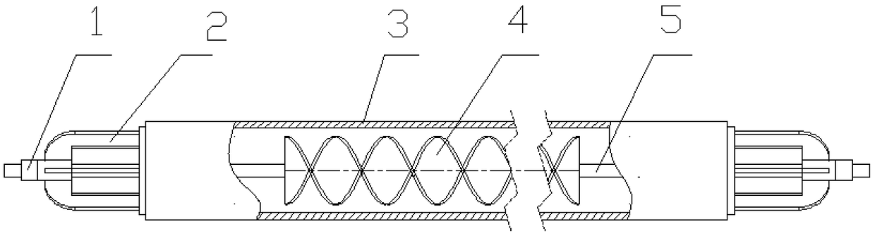
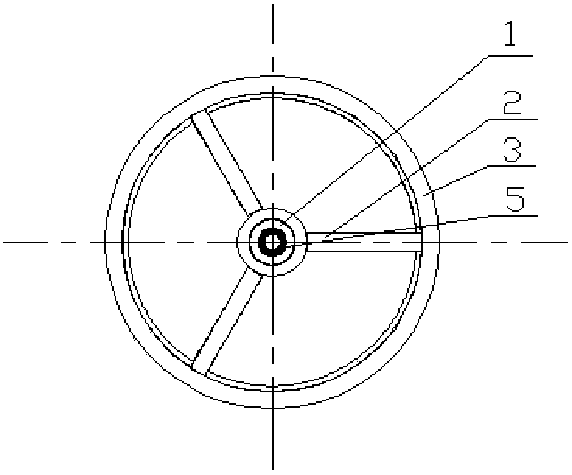
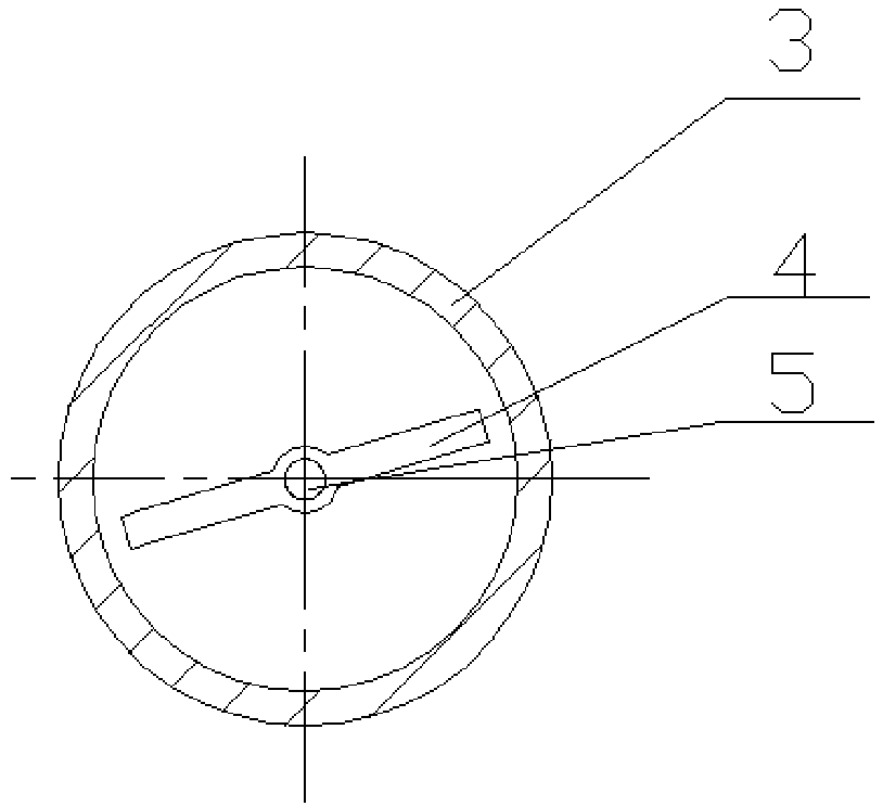
[0022] Such as Figure 1 to Figure 8 As shown, it includes a limit piece 1, a support frame 2, a heat transfer tube 3, a helical twisted belt 4, a reinforced skeleton core 5, and a bone spur 6; the helical twisted belt 4 and the flexible shaft 5 are continuously connected through the cable coating technology. Production and consolidation of the spiral twisted belt 4 and the reinforced skeleton shaft core 5, wherein the part of the reinforced skeleton shaft core protruding from the spiral twisted strip is used as the mandrel.

[0023] Such as figure 1 As shown in the installation schematic diagram, the support frame 2 is installed on both ends of the heat transfer tube 3 through interference fit, the mandrel passes through the inner hole of the support frame 2, and the limiter 1 is fixed on the mandrel on the outside of the support frame 2. For axial positioning, the fixing method of the limiting member 1 and the mandrel is riveting, bonding, adhesion or screw connection, and ...


PUM


Abstract

The invention relates to a spiral twisting belt embedded with a reinforced framework shaft core. The spiral twisting belt comprises a spiral twisting belt body, the reinforced framework shaft core andan axial positioning device, wherein the axial positioning device comprises a supporting rod and a limiting part; the spiral twisting belt and the reinforced framework shaft core are fixedly connected into an integer; the part, extending out of the spiral twisting belt, of the reinforced framework shaft core is taken as a mandrel; supporting frames are mounted at the two ends of a heat transmitting tube through interference fit; and the mandrel passes through inner holes of the supporting frames for fixing the limiting part on the mandrel at the outer sides of the supporting frames for axially positioning the limiting part. The spiral twisting belt body is embedded with the reinforced framework shaft core, so that strength and rigidity of the spiral twisting belt are enhanced, deflectionof the twisting belt is reduced, and severe scratch and abrasion, on the tube wall, of the spiral twisting belt is reduced; besides, the contact surfaces between the limiting part and the supporting frames are small, so that friction loss is small; and disturbance of liquid is increased as spiral flow is generated by liquid in a runner of the spiral twisting belt body, so that turbulence degree ofthe liquid in the tube is further increased, and therefore, heat exchange efficiency is improved.

Description

technical field [0001] The invention relates to a heat exchange tube insert in heat exchange equipment such as a shell-and-tube heat exchanger and a heat exchange reactor, and particularly relates to a heat exchange tube insert that uses the fluid in the heat exchange tube as a driving force. The on-line self-cleaning enhanced heat transfer spiral twisted ribbon in the heat transfer tube belongs to the field of enhanced heat transfer. Background technique [0002] At present, heat exchange equipment such as heat exchangers and heat exchange reactors are widely used in thermal power, nuclear power, petroleum, chemical industry, metallurgy, food, pharmaceuticals, light industry, ship power, aerospace and other fields. The phenomenon of dirt deposition in the heat exchange tube is very common. The scaling on the wall of the heat exchange tube increases the thermal resistance of the tube side, and also increases the flow resistance of the liquid in the heat exchange tube. With t...

Claims


Application Information

Patent Timeline
IPC IPC(8): F28F13/02F28F13/12F28G3/10F28G15/02
CPCF28F13/02F28F13/12F28G3/10F28G15/02
Inventor 杨卫民阎华关昌峰丁秦左夏华李鹏飞曹如楼丁玉梅
Owner BEIJING UNIV OF CHEM TECH
Learn More