
Automation engineering monitoring device

A technology of automation engineering and monitoring devices, which is applied in the direction of measuring devices, instruments, signal transmission systems, etc., can solve the problems of troublesome installation and fixing of monitoring equipment, and the inability to send monitoring information to the control center in a timely and accurate manner, so as to achieve the effect of ensuring work efficiency

Inactive Publication Date: 2018-11-06
葛明均
View PDF5 Cites 1 Cited by
  • Summary
  • Abstract
  • Description
  • Claims
  • Application Information

AI Technical Summary

Problems solved by technology

[0005] The purpose of the present invention is to solve the problem that the internal structure of the automatic engineering monitoring device in the prior art is relatively simple, the installation and fixation of the monitoring equipment is relatively troublesome when monitoring the project, and the monitored information cannot be sent to the control center in time and accurately. An automated engineering monitoring device proposed

Method used


Image

  • Automation engineering monitoring device
  • Automation engineering monitoring device
  • Automation engineering monitoring device

Examples


Embodiment 1

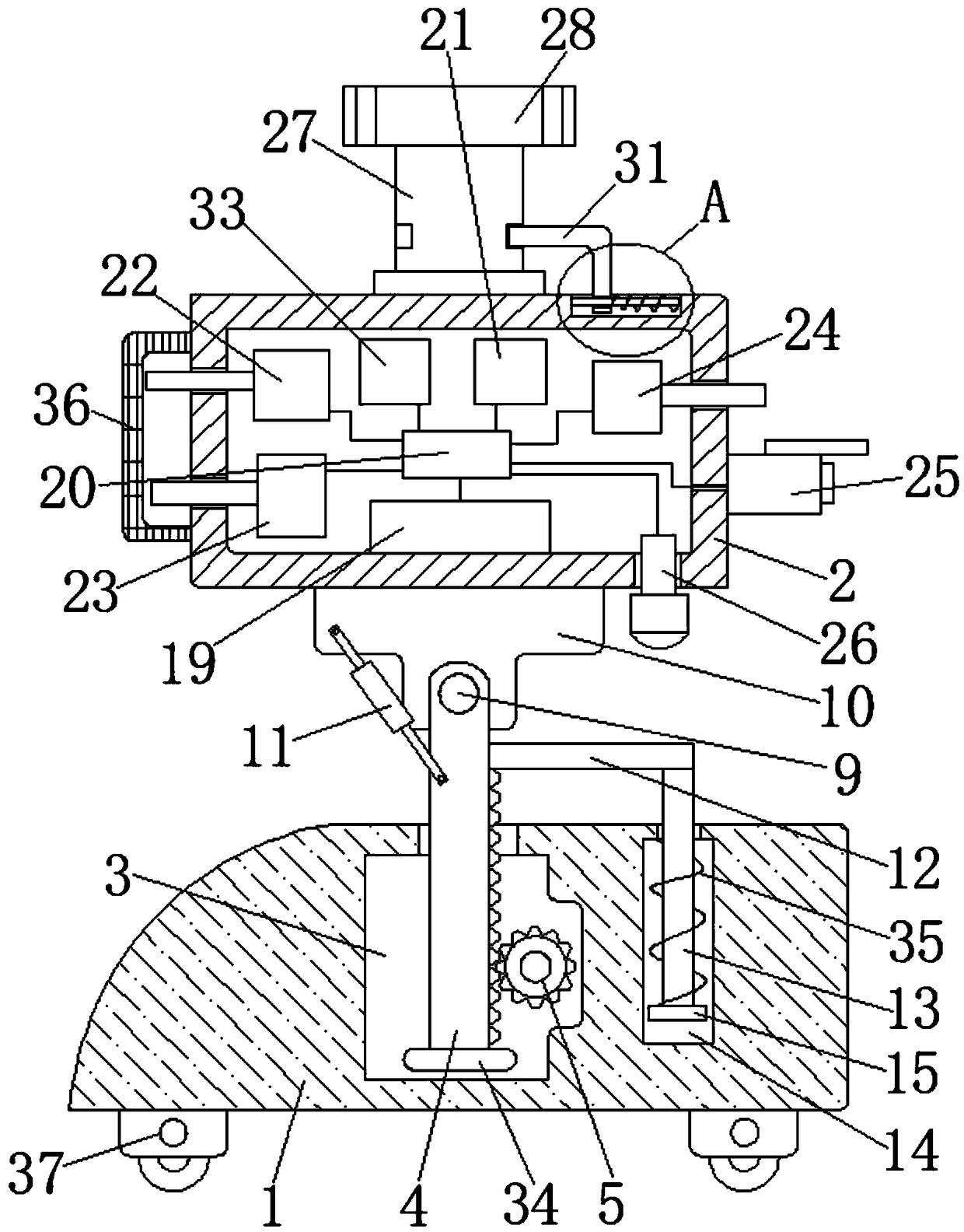
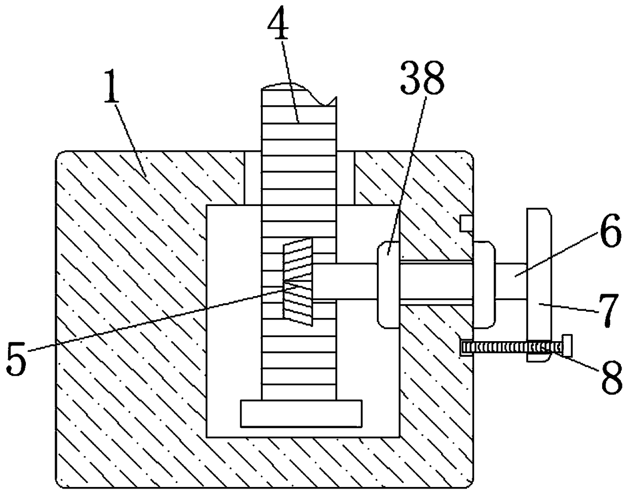
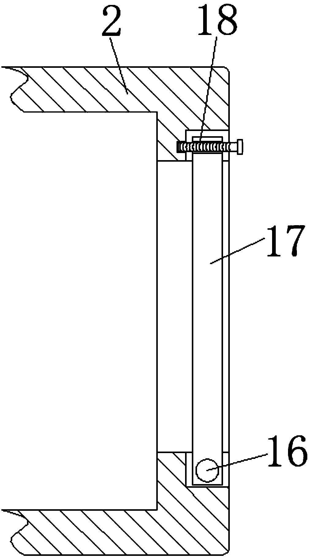
[0034] refer to Figure 1-4 , an automatic engineering monitoring device, comprising a base 1 and a device box 2, the device box 2 is horizontally arranged above the base 1, a cavity 3 is provided in the base 1 for setting a rack and wheel 4, and the cavity 3 is slidingly connected There is a gear rack 4, which is used to drive the support block 10 to move, and a gear 5 meshing with the gear rack 4 is arranged in the cavity 3, and is used to drive the gear rack 4 to move, and the inner wall of the gear 5 and the cavity 3 passes through the rotating Rod 6 is rotationally connected to drive gear 5 to rotate. The end of rotary rod 6 away from gear 5 penetrates the inner wall of cavity 3 and extends outward. The extended end of rotary rod 6 is fixedly connected with handle 7 for driving rotary rod 6 to rotate. The handle 7 is threaded with a first locking screw 8 for fixing the handle 7, the outer wall of the base 1 is surrounded by a plurality of thread grooves corresponding to t...


PUM


Abstract

The invention discloses an automation engineering monitoring device, and the device comprises a pedestal and a device box. The device box is horizontally disposed above the pedestal. The pedestal is provided with a cavity, and the interior of the cavity is slidably connected with a gear rack. A gear which is engaged with the gear rack is disposed in the cavity, and the gear is rotatably connectedwith the inner wall of the cavity by a rotating rod. One end, far from the gear, of the rotating rod passes through the inner wall of the cavity and extends outwards, and the extending end of the rotating rod is fixedly connected with a handle, wherein the handle is in threaded connection with a first locking screw. The outer wall of the pedestal is surrounded by a plurality of threaded slots corresponding to the first locking screw, and one end of the gear rack passes through the inner top of the cavity and extends outwards. The setting of a plurality of detection mechanisms enables the device to carry out the accurate and timely monitoring of the engineering conditions, transmits the data timely to a control center, and guarantees the work efficiency of the engineering detection.

Description

technical field [0001] The invention relates to the technical field of engineering monitoring, in particular to an automatic engineering monitoring device. Background technique [0002] Engineering monitoring refers to the technical means of using monitoring instruments to monitor various control indicators of key parts during the construction of buildings and structures. This technical means is used to check whether the construction process is reasonable and to ensure the safety of construction. In recent years, wireless monitoring technology in the field of engineering monitoring technology has been gradually popularized and applied. At the same time, with the continuous improvement of industrial production automation and the rapid popularization of intelligence, industrial sites need to deploy a large number of monitoring equipment such as sensors and instruments to monitor various parameters. [0003] However, the internal structure of the existing automatic engineering...

Claims


Application Information

Patent Timeline
IPC IPC(8): G01D21/02G08B19/00G08C17/02
CPCG01D21/02G08B19/005G08C17/02
Inventor 葛明均林国栋
Owner 葛明均
Learn More