
Fiber connecting flange and light extracting module

A technology of optical fiber connection and flange, which is applied in the field of optical fiber communication, can solve the problems of optical link failure, loss of communication optical communication signal strength, etc., and achieve the effect of ensuring transmission quality, low loss rate, and signal quality

Pending Publication Date: 2018-11-06
南京锦龙装饰工程有限公司
View PDF0 Cites 4 Cited by
  • Summary
  • Abstract
  • Description
  • Claims
  • Application Information

AI Technical Summary

Problems solved by technology

Some detection light extraction technologies that exist at present realize the detection light extraction at the cost of destroying or changing the structure of the optical fiber and its transmission path, that is, the leakage of communication light is created by forcibly cutting the optical fiber and its outer ferrule The exit is used to obtain the leaked communication light as the detection light, but since the intensity of the communication light emitted by the optical transmitter is fixed in each optical fiber transmission path, and there are multiple active connection points in the optical fiber transmission path, the optical fiber joint is relatively Many, if the detection light is extracted directly at the active connector in this way of cutting the optical fiber, it will not only greatly damage the communication signal strength of the communication light, but also cause the original normal communication optical link to fail: optical cat Retired because the working optical power could not be reached

Method used


Image

  • Fiber connecting flange and light extracting module
  • Fiber connecting flange and light extracting module
  • Fiber connecting flange and light extracting module

Examples


Embodiment Construction

[0044] In order to make the above objects, features and advantages of the present invention more comprehensible, specific implementations of the present invention will be described in detail below in conjunction with the accompanying drawings.

[0045] In the following description, a lot of specific details are set forth in order to fully understand the present invention, but the present invention can also be implemented in other ways different from those described here, and those skilled in the art can do it without departing from the meaning of the present invention. By analogy, the present invention is therefore not limited to the specific examples disclosed below.

[0046] Second, "one embodiment" or "an embodiment" referred to herein refers to a specific feature, structure or characteristic that may be included in at least one implementation of the present invention. "In one embodiment" appearing in different places in this specification does not all refer to the same emb...


PUM


Abstract

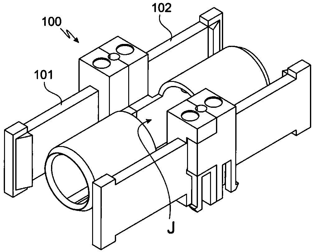
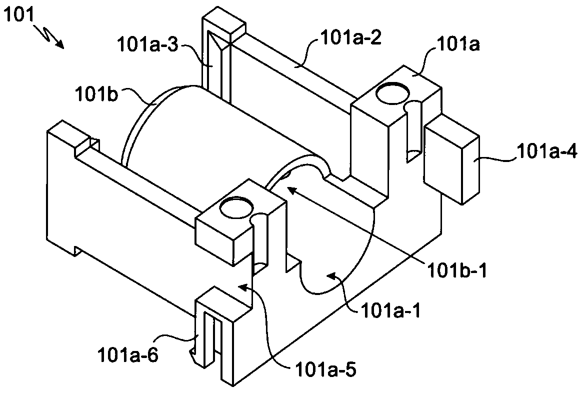
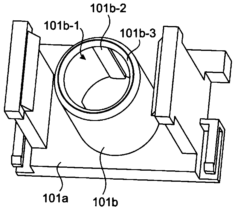
The invention discloses a fiber connecting flange comprising a coupling assembly. The coupling assembly comprises a first connecting member and a second connecting member which are centrally symmetrical when connected. The first connecting member comprises a first connecting portion and a first clamping portion. The first clamping portion has a first through hole therein axially perpendicular to afirst inner side surface. The upper end of the first connecting portion is provided with a recessed notch corresponding to the width and the position of the first clamping portion. The bottom of thenotch is in communication with the first through hole. The fiber connecting flange of the invention can be freely replaced in an original flange tray without changing the structure of the flange tray.Within a flange insertion loss standard value, a detection light wave in an optical fiber can be extracted and recognized. The fiber connecting flange is configured to gradually replace an existing mechanical flange so that the flange can be provided with eyes to lay a solid foundation for more bloated ODN intellectualization.

Description

technical field [0001] The invention relates to the technical field of optical fiber communication, in particular to an optical fiber connecting flange and an optical module. Background technique [0002] In recent years, in the field of communication, optical fiber capable of high-speed and large-capacity transmission has become the mainstream of transmission lines and is being further developed. As a result, especially in optical communication related equipment such as data centers or telecommunication equipment rooms, construction work such as frequent changes, abandonment, and addition of optical transmission paths is carried out. The current management method is to stamp paper on jumpers. label to manage the optical fiber communication direction address and transmission content of this port, but the workload increases sharply due to a large number of changes or the need to re-print paper labels for demolition and construction operations, and the actual operator's mistak...

Claims


Application Information

Patent Timeline
Patent Type & Authority Applications(China)
IPC IPC(8): G02B6/38
CPCG02B6/3825G02B6/385G02B6/387
Inventor 王昌涔
Owner 南京锦龙装饰工程有限公司
Learn More