Supercharge Your Innovation With Domain-Expert AI Agents!

Cooling control apparatus for exposure table surface in exposure machine

A technology of cooling control and exposure machine, which is applied in the direction of photo-plate-making process exposure device, photo-plate-making process of pattern surface, optical mechanical equipment, etc., which can solve problems such as temperature unevenness, image PCB expansion and contraction, and board failure, and achieve Simple structure, improved PCB expansion and contraction, novel design effects

Inactive Publication Date: 2018-11-06
东莞市多普光电设备有限公司
View PDF4 Cites 0 Cited by
  • Summary
  • Abstract
  • Description
  • Claims
  • Application Information

AI Technical Summary

Problems solved by technology

[0002] In the field of PCB manufacturing equipment, equipment for exposing PCBs has appeared. At present, the common exposure table cooling devices in the exposure machine in the industry are mechanical air cooling; Due to the poor cooling effect and the ink printed on the surface of the PCB before exposure is not dry (required by the process design, dryness will cause poor exposure), it is easy to stick to the exposure table, causing the sucker mechanism to take the board. Failure and the appearance of ink on the PCB surface, so it is necessary to improve the cooling control method of the exposure table

Method used


Image

  • Cooling control apparatus for exposure table surface in exposure machine
  • Cooling control apparatus for exposure table surface in exposure machine
  • Cooling control apparatus for exposure table surface in exposure machine

Examples


Embodiment Construction

[0024] The present invention will be described below in conjunction with specific embodiments.

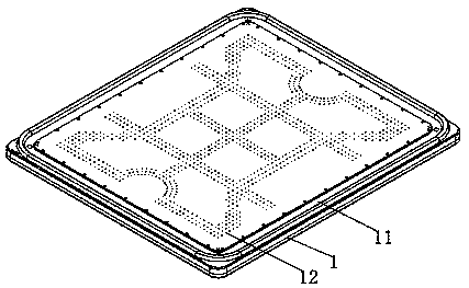
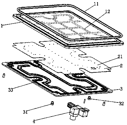
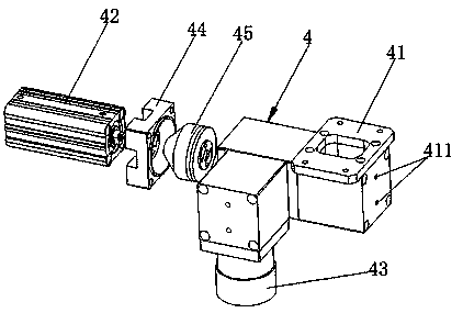
[0025] Such as Figure 1-3 As shown, a cooling control device applied to the exposure table in an exposure machine includes a middle frame 1, a middle frame sealing strip 11 is installed on the upper end of the middle frame 1, a heat dissipation plate 2 is installed on the lower end, and a heat dissipation plate 2 is installed on the lower end. There is a bottom plate 3, the lower end of the bottom plate 3 is equipped with a water inlet 31 and a water outlet 32, and the lower end of the bottom plate 3 is equipped with a device for controlling the positive and negative pressure between the cooling plate 2 and the middle frame 1 and part of the water vapor attached to the cooling plate 2 The gas-liquid splitting device 4, the gas-liquid splitting device 4 is provided with a switcher 41 installed at the lower end of the base plate 3, the switcher 41 is connected with a cylinder 42 and...


PUM


Abstract

The invention discloses a cooling control apparatus for an exposure table surface in an exposure machine. The cooling control apparatus comprises a middle frame, wherein the upper end of the middle frame is provided with a middle frame sealing glue strip, the lower end of the middle frame is provided with a heat dissipation plate, the lower end of the heat dissipation plate is provided with a bottom plate, the lower end of the bottom plate is provided with a water inlet and a water outlet, the lower end of the bottom plate is provided with a gas-liquid flow dividing device for controlling thepositive and negative pressure between the heat dissipation plate and the middle frame and partial water vapor attached to the heat dissipation plate, the gas-liquid flow dividing device is provided with a switching device arranged on the lower end of the bottom plate, the switching device is connected to a gas cylinder and a vacuum gas suction port, the gas cylinder is fixed on the upper end of the switching device through a piston seat, and a cone-shaped piston is arranged between the piston seat and the switching device. According to the present invention, the cooling control apparatus hasadvantages of novel design, simple structure and the like, can control the exposure table surface temperature within the range, and can further improve the objective problem of the negative pressure formed due to vacuumizing during exposure so as to substantially improve the image PCB expansion-shrinkage and sticking on the board due to the heat generated during the exposure, and the positioning precision of the board taking and placing.

Description

technical field [0001] The invention relates to the technical field of PCB manufacturing equipment, in particular to a cooling control device applied to an exposure table in an exposure machine. Background technique [0002] In the field of PCB manufacturing equipment, equipment for exposing PCBs has appeared. At present, the common exposure table cooling devices in the industry are mechanical air cooling; during the air cooling process, there are dead angles and uneven temperature, so that the image PCB expands and shrinks, and at the same time Due to the poor cooling effect and the ink printed on the surface of the PCB before exposure is not dry (required by the process design, dryness will cause poor exposure), it is easy to stick to the exposure table, causing the sucker mechanism to take the board. Failure and imaging the appearance of the ink on the PCB surface, so it is necessary to improve the cooling control method of the exposure table. Contents of the invention ...

Claims


Application Information

Patent Timeline
IPC IPC(8): G03F7/20
CPCG03F7/70875
Inventor 陈振才
Owner 东莞市多普光电设备有限公司
Features
  • R&D
  • Intellectual Property
  • Life Sciences
  • Materials
  • Tech Scout
  • Unparalleled Data Quality
  • Higher Quality Content
  • 60% Fewer Hallucinations
Learn More