Calculation method for plant cavitation factor of through-flow turbine

A tubular turbine and cavitation coefficient technology, which is applied in the directions of calculation, electrical digital data processing, design optimization/simulation, etc., can solve the problem that the cavitation coefficient cannot be selected correctly, the power station cavitation coefficient is difficult to meet the new hydropower engineering requirements, and the results are different, etc. question

Inactive Publication Date: 2018-11-06
POWERCHINA CHENGDU ENG
View PDF6 Cites 5 Cited by
  • Summary
  • Abstract
  • Description
  • Claims
  • Application Information

AI Technical Summary

Problems solved by technology

Since this method estimates the cavitation coefficient σ of the power station according to the statistical formula p , there are many statistical formulas of this kind at present, because the water turbine parameter sample data on which each statistical formula is based is before the 1970s and 1980s or a certain water head section or a certain specific speed n s range, there are certain limitations, the results estimated by different statistical formulas for the same hydropower project are different, and some even have large differences, so it is impossible to correctly select
Therefore, both methods 1 and 2 cannot meet the requirements of hydropower engineering for the continuous development of new technologies, new materials, new processes, and new structures. The estimated cavitation coefficient σ p Generally, it is also difficult to meet the new hydropower engineering requirements

Method used


Image

  • Calculation method for plant cavitation factor of through-flow turbine
  • Calculation method for plant cavitation factor of through-flow turbine
  • Calculation method for plant cavitation factor of through-flow turbine

Examples


Embodiment Construction

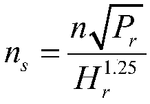
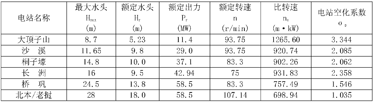
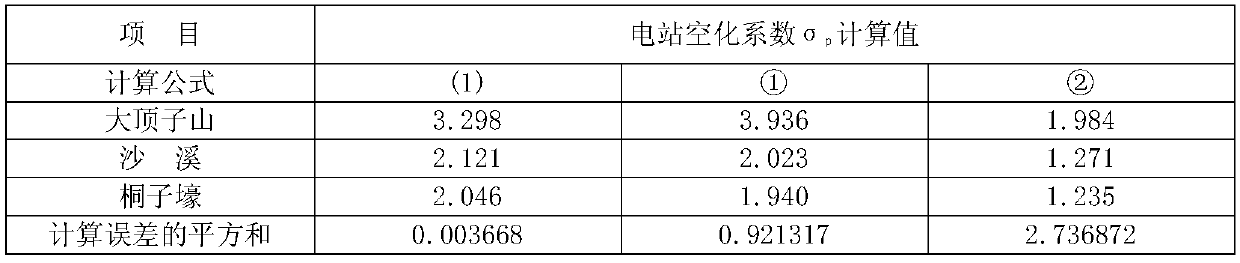
[0013] The present invention first collects and organizes the data of a large number of domestic and foreign well-running tubular water turbine generating sets in the past 30 years, according to the maximum application water head H of the water turbine. max , divide the data into H max ≤15m and H max For two groups > 15m, the least square method is used to use a large number of turbine parameters as sample data, and regression statistics are used to obtain the cavitation coefficient σ of the hydropower station at the two water head sections p Calculation formula: when H max ≤15m, σ p =3.7004×ln(n s )-23.135(1); when H max >15m, σ p =3.6575×ln(n s )-22.84(2), after doing a lot of calculation and derivation work in the early stage, a more reasonable calculation method was creatively summarized for the cavitation coefficient of the tubular hydro turbine power station. Since the present invention will H max The range is divided, so the tubular turbines corresponding to dif...


PUM


Abstract

The invention relates to a water turbine for a hydropower station, and discloses a calculation method for a plant cavitation factor of a through-flow turbine. The plant cavitation factor of the through-flow turbine is more reasonably calculated to meet new hydropower engineering requirements. The method comprises the following steps of determining a specific speed of the through-flow turbine, andmarking the specific speed as ns; determining a biggest applied water head of the through-flow turbine, marking the biggest applied water head as Hmax, and judging a range of the Hmax; and calculatingthe plant cavitation factor according to a plant cavitation factor calculation formula of the range corresponding to the Hmax, and marking the plant cavitation factor as sigma p, wherein the plant cavitation factor calculation formula of the range is as follows: when the Hmax is less than or equal to 15m, the sigma p is equal to 3.7004Xln (ns)-23.135; when the Hmax is greater than 15m, the sigmap is equal to 3.6575Xln(ns)-22.84. The method is suitable for calculating the plant cavitation factor of the through-flow turbine, so that the new hydropower engineering requirements can be better met.

Description

technical field [0001] The invention relates to a water turbine in a hydropower station, in particular to a calculation method for the cavitation coefficient of a tubular water turbine power station. Background technique [0002] In a hydropower station equipped with a tubular turbine, the installation elevation of the turbine is the elevation of the centerline of the main shaft of the turbine, and the suction height of the turbine is the elevation difference from the highest point of the runner blade to the tailwater level of the power station. Raising the suction height and installation elevation of the turbine can reduce the underwater engineering volume and investment of the main powerhouse; while reducing the suction height and installation elevation of the turbine can improve the cavitation performance of the turbine, which is conducive to the stable operation of the unit and prolongs the service life of the unit. Therefore, how to reasonably determine the suction heig...

Claims


Application Information

Patent Timeline
IPC IPC(8): G06F17/50
CPCG06F30/20
Inventor 董宏成蒋登云田迅孙文彬刘丁
Owner POWERCHINA CHENGDU ENG
Why Eureka
Try Eureka