
Planar microstrip transmission array antenna

An array antenna and microstrip technology, which is applied in the field of planar microstrip transmission array antenna, can solve the problems of narrow working frequency band and inability to realize beam scanning, etc., and achieve the effect of wide-band transmission and large-angle scanning and tracking of beams

Active Publication Date: 2018-11-06
UNIV OF ELECTRONICS SCI & TECH OF CHINA
View PDF4 Cites 4 Cited by
  • Summary
  • Abstract
  • Description
  • Claims
  • Application Information

AI Technical Summary

Problems solved by technology

[0005] The technical problem to be solved by the present invention is the technical problem that the working frequency band is narrow and beam scanning cannot be realized in the prior art

Method used


Image

  • Planar microstrip transmission array antenna
  • Planar microstrip transmission array antenna
  • Planar microstrip transmission array antenna

Examples


Embodiment 1

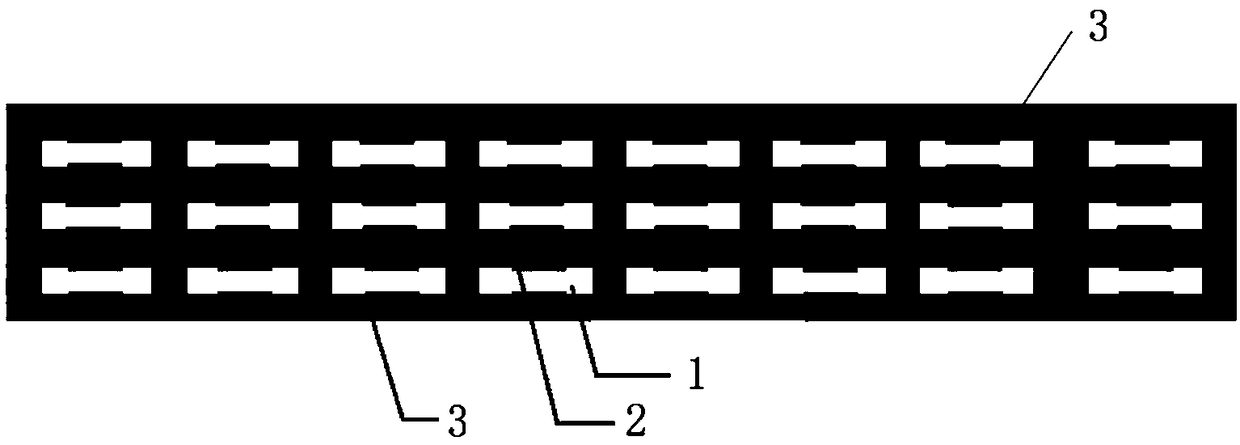
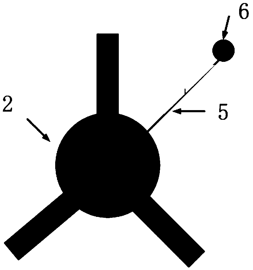
[0026] This embodiment provides a planar microstrip transmission array antenna, such as Figure 9 , the planar microstrip transmission array antenna includes a feed and a microstrip transmission array located in front of the feed; as figure 1 , the microstrip transmissive array includes a plurality of multilayer frequency selective surfaces 4 loaded with liquid crystal cells, such as figure 2 , the multilayer frequency selective surface units 4 are arranged in an array, and the liquid crystal units are fed with a bias voltage. The planar microstrip transmission array antenna converts the quasi-spherical wave radiated by the feed source into a quasi-plane wave through the phase compensation of each unit, so as to achieve directivity.

[0027] The feed source determines the design of the transmission surface. The feed source of this embodiment requires radiation stability, and the bandwidth, cross-polarization level, etc. should also be satisfied. Because the horn antenna ha...


PUM


Abstract

The invention relates to a planar microstrip transmission array antenna. By the planar microstrip transmission array antenna, the technical problems that a traditional microstrip planar transmission array is narrow in working frequency band and beam scanning cannot be achieved are solved. The planar microstrip transmission array antenna is implemented by employing a feeding source and a crystal liquid microstrip transmission array, the crystal liquid microstrip transmission array is arranged in front of the feeding source, the microstrip transmission array comprises a plurality of multi-layerfrequency selective surfaces loaded with multi-layer crystal liquid units, and the multi-layer frequency selective surfaces are arranged in an array way. By the adoption of the technical scheme employing liquid crystal units to bias voltage feeding, synchronous control of multi-layer liquid crystal is achieved, the problem is solved very well, and the planar microstrip transmission array antenna can be applied into a lens antenna.

Description

technical field [0001] The invention relates to the field of antennas, in particular to a planar microstrip transmission array antenna. Background technique [0002] The lens antenna is an end-fire antenna that loads a medium on the antenna feed and changes the electromagnetic beam of the feed through the transmission of the medium. However, due to the large volume and low efficiency of the traditional transmission antenna, it is difficult to be used in engineering practice. With the development of printed circuit technology, microstrip arrays have the advantages of low profile and high efficiency. Microstrip patch arrays can replace traditional dielectric lens antennas to make up for their shortcomings. The planar microstrip transmission array antenna is a spherical wave-plane wave conversion system composed of a feed source and a microstrip transmission array. Through the phase compensation of each antenna element of the transmission array, the near-field spherical wave o...

Claims


Application Information

Patent Timeline
Patent Type & Authority Applications(China)
IPC IPC(8): H01Q15/00H01Q21/00
CPCH01Q15/0013H01Q15/0026H01Q21/00
Inventor 蒋迪傅子豪刘宇鹏李潇雨王振
Owner UNIV OF ELECTRONICS SCI & TECH OF CHINA
Learn More