An on-load tap changer and method thereof

An on-load tap and switch technology, applied in electronic switches, pulse technology, semiconductor devices, etc., can solve problems such as complex structure, achieve the effects of small size, reduced heat generation, and simple mechanical structure

Active Publication Date: 2021-06-01
李晓明
View PDF6 Cites 0 Cited by
  • Summary
  • Abstract
  • Description
  • Claims
  • Application Information

AI Technical Summary

Problems solved by technology

[0005] However, the various arc-free on-load tap-changers proposed at present, like the traditional on-load tap-changers, all include a shared switch, and the structure is still complicated

Method used


Image

  • An on-load tap changer and method thereof
  • An on-load tap changer and method thereof
  • An on-load tap changer and method thereof

Examples


Embodiment 1

[0070]For the convenience of the narrative, the pressure-regulator transformer with a 5-point joint is expressed as an example of the first structure and the simple-loaded switching switch structure and the working principle. Of course, in other embodiments, the number of points can be replaced, reduced, or increased, and this data is only set to facilitate the description, and is not limited thereto.

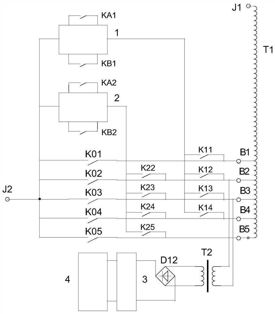
[0071]The first structure is simple, and the unloaded system is connected.figure 1 Indicated. The two terminals J1 and J2 connecting the power system for the pressure regulator transformer, one end of the pressure regulator coil of the pressure transformer connection J1; one of the five main switches of the first structure, the secondary switching switch, respectively, connected to the pressure regulator transformer The other end of the five sizes B1, B2, B3, B4, B5, B6, and 5 main switches are connected to the terminal J2; any main switch is closed, the pressure regulating circuit of t...

Embodiment 2

[0096]For the convenience of the description, the pressure regulator transformer with a 5-point joint is expressed as an example, and the third structure is simple, and the principle of operation is concluded.

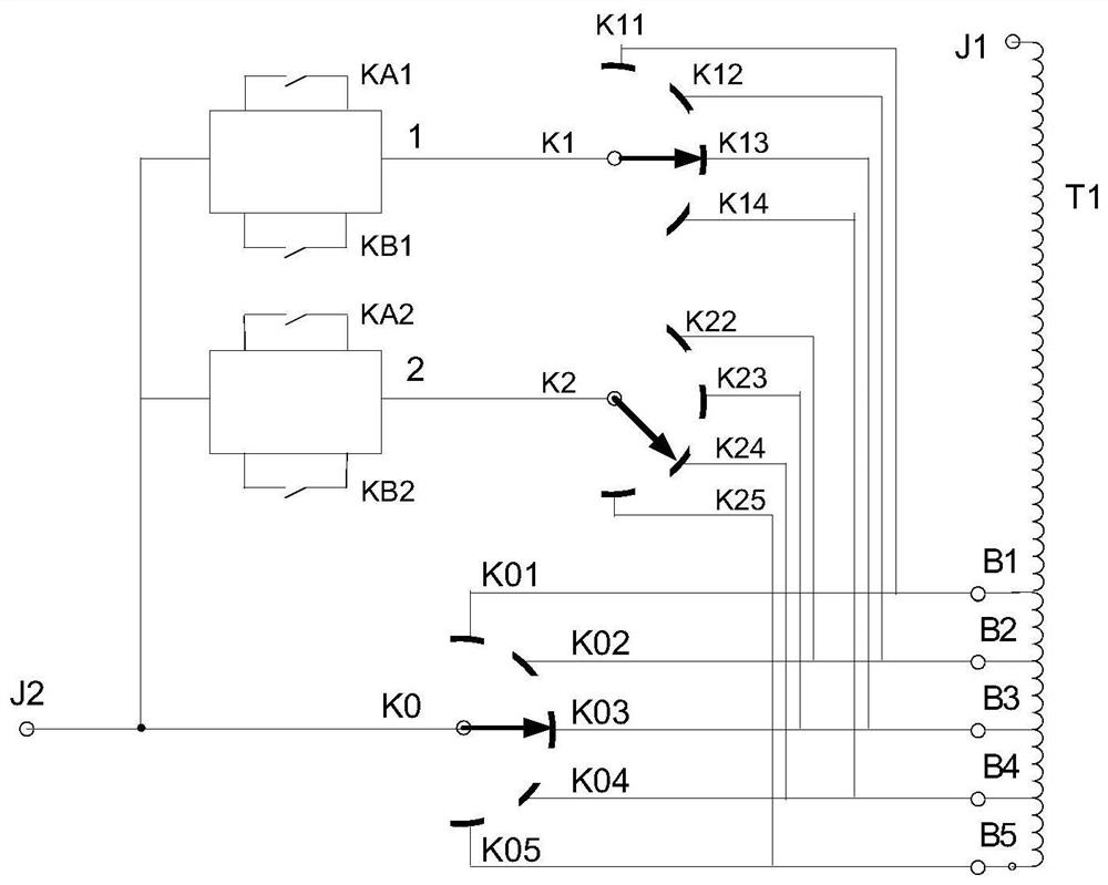
[0097]The third structure is simple, and the connection is connected.Figure 4 Indicated. The two terminals J1 and J2 connecting the power system, one end of the pressure regulating coil of the pressure regulator transformer connects J1; the third structure is simple, and one end of the five main switches inside the interior of the tidal switch is connected to the pressure regulator transformer. The other end of the five sizes B1, B2, B3, B4, B5, B6, and 5 main switches are connected to the terminal J2; any main switch is closed, the pressure regulating circuit of the pressure transformer can flow; different main opening off When the pressure regulator transformer outputs different voltages, in the order of voltage, the main switch number sequence is arranged as K01, K02, K03, K...

Embodiment 3

[0107]Sixth Structure Simple DIST is used for the pressure regulating transformer socket in the middle of the pressure regulating coil. For the convenience of the narrative, the pressure regulator transformer with 6-point joint is expressed as an example, and the third structure is simple, and the principle of operation is concluded.

[0108]The sixth structure is simple and the connected switch structure, such asFigure 7 Indicated. The pressure regulator transformer has two terminals J1 and J2 connection power system, and the end connection terminal J1 of the upper regulator of the pressure transformer has the lower end of the upper regulating coils, and the lower pressure regusal of the pressure transformer. The start end of the coil has the end connection terminal J2 of the splitting B2, B4, B6, and the lower regulator coil; the sixth structurally simple, the 5 main switches inside the connected switching switch are in series, and the six nodes formed are respectively and adjusted. ...


PUM


Abstract

The invention discloses an on-load tap changer and a method thereof, comprising a main switch, a thyristor auxiliary circuit, and a selector switch; each main switch is respectively connected in series in different circuits of a voltage regulating coil of a voltage regulating transformer through at least one tap; all When any one of the main switches is closed, the voltage regulating coil can form a current flow path; when different main switches are closed, the voltage regulating transformer outputs different voltages; One main switch can be connected in parallel with another thyristor auxiliary circuit through the selector switch; two switchers are formed which are respectively connected in parallel with the main switch of the thyristor auxiliary circuit; the shared switcher is not included inside the on-load tap changer; each switch is operated in sequence to realize the load The current is switched on-load from the originally closed main switch to the closing main switch.

Description

Technical field[0001]The present invention relates to an on-load tap switch and a method thereof.Background technique[0002]The operating mode of the power system can cause changes in the bus voltage. The power system has a strict requirement for the variation range of the bus voltage, and therefore, the technology of the bus voltage is required. The mode of changing the power transformer tacit is carried out is a voltage regulation measures widely used in the power sector. Under the conditions of the transformer with load current (contained), switch the split of a voltage of the transformer to another voltage, and to ensure that the switching process power user does not stop power, it is necessary to use a high-tech content with a carry-down switch. (on-load tap changer).[0003]It is currently widely used in the world with a resistive withdrawal. The resistive has a load-bearing switch is a switching process of two different voltage dividing connections in a manner transition. This m...

Claims


Application Information

Patent Timeline
Patent Type & Authority Patents(China)
IPC IPC(8): H03K17/081H03K17/72H03K17/00
CPCH03K17/007H03K17/08108H03K17/72H03K2217/0081H03K17/08116
Inventor 李晓明
Owner 李晓明
Why Eureka
Try Eureka