Edge cutting device for production of sun-shading roller shutter

A sunshade roller blind and edge cutting technology, which is applied in metal processing and other directions, can solve the problems that the cloth is easy to be trampled and dirty, and the cutting width cannot be adjusted, so as to achieve the effect of shortening the working time, simple structure and convenient operation

Inactive Publication Date: 2018-11-09
湖州多玛智能科技股份有限公司
View PDF1 Cites 0 Cited by
  • Summary
  • Abstract
  • Description
  • Claims
  • Application Information

AI Technical Summary

Problems solved by technology

[0004] The purpose of the present invention is to solve the disadvantages in the prior art that the cutting width cannot be adjusted and the cloth directly falls on the ground after cutting and is easy to be stepped on and dirty, and proposes a side cutting device for the production of sunshade roller blinds

Method used


Image

  • Edge cutting device for production of sun-shading roller shutter
  • Edge cutting device for production of sun-shading roller shutter
  • Edge cutting device for production of sun-shading roller shutter

Examples


Embodiment 1

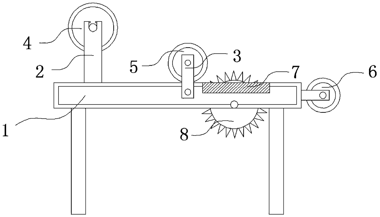
[0027] Embodiment 1, insert the roller shaft in the middle of the roller blind roller 4 that needs to be cut, and hang it in the groove of the installation pole 2. The shaft 11 moves into the side support rod 9 (the insertion shaft 11 can move with the rotating handle 12, and the part of the side support rod 9 is positioned at the side of the insertion shaft 11 is opened), and then another person plugs one end of the winding roller 6 into the second position. Place the rewinding roller 6 flat on a rotating shaft 10, and then push the rotating handle 12 to insert the insertion shaft 11 into the other side of the rewinding roller 6. When the bullet 14 moves to the empty hole 13 with the push of the rotating handle 12 , ejected under the elastic action of the spring on one side, at this time, the turning handle 12 is no longer pushed, and the insertion shaft 11 is also inserted into the inside of the winding roller 6, the trimming wheel 8 is started, and then the roller blind roll...

Embodiment 2

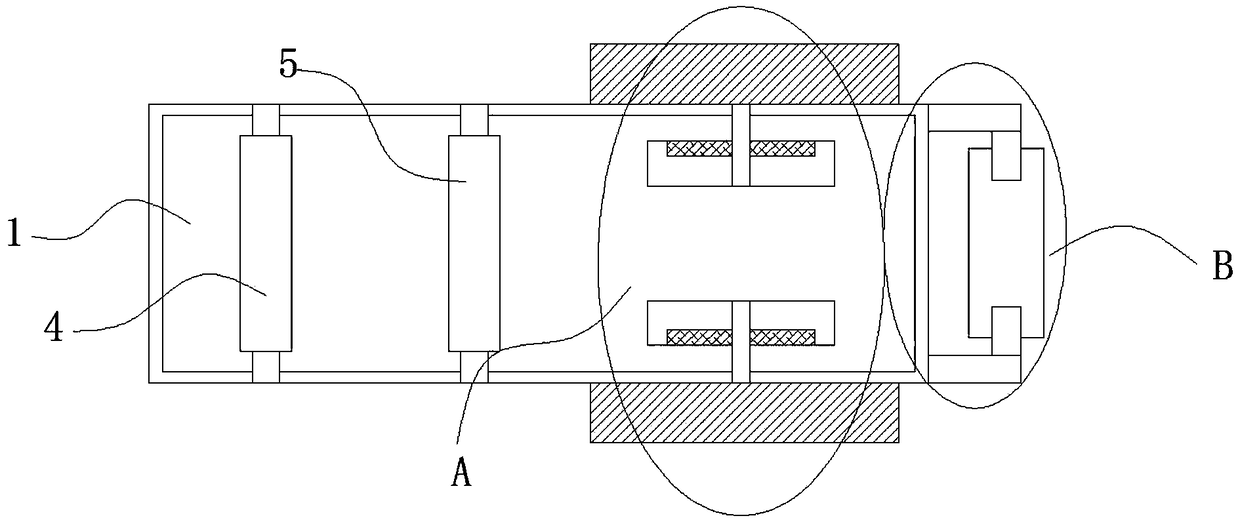
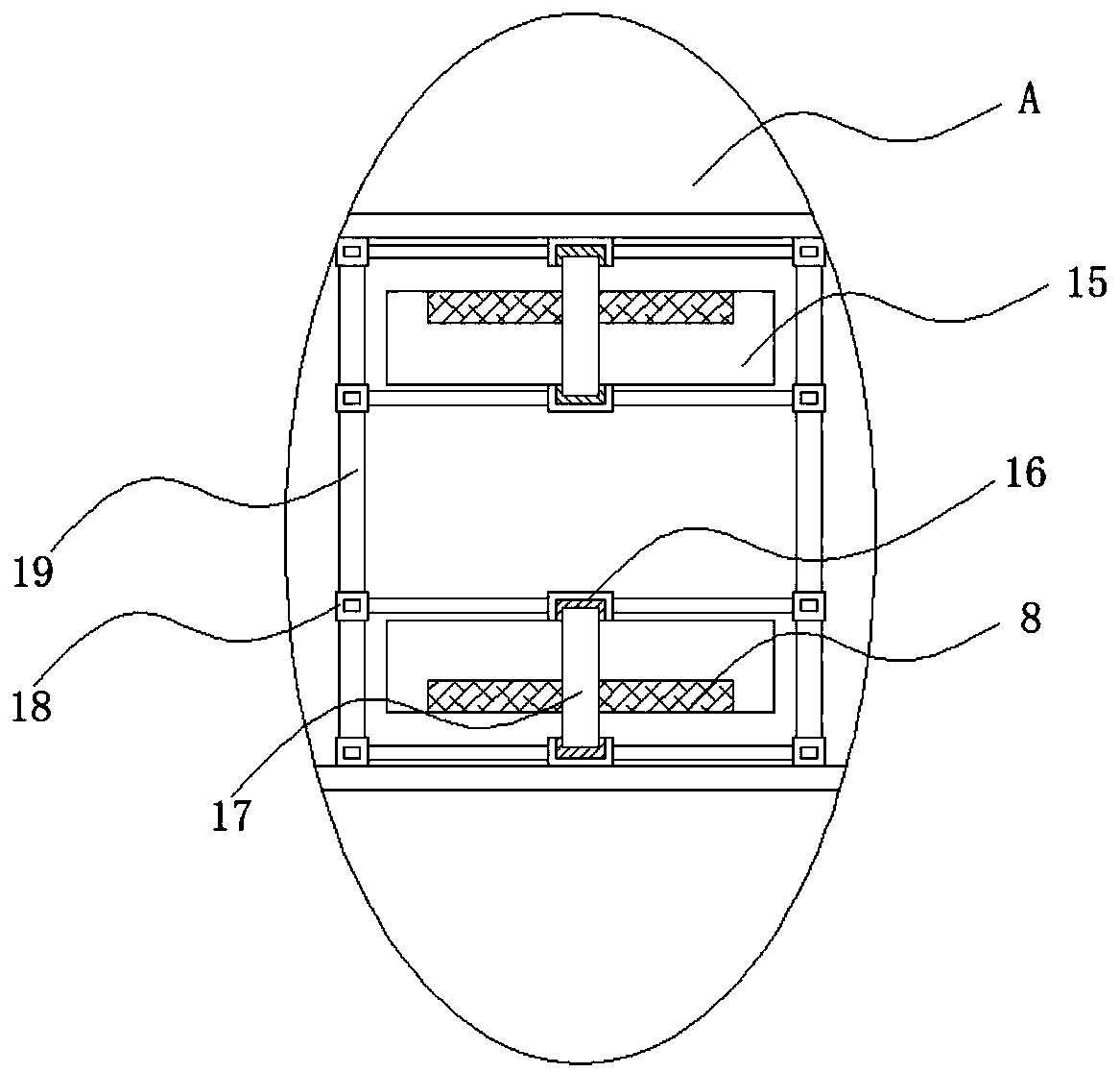
[0028]Embodiment 2, when it is necessary to cut roller blind sides of different widths, manually use a ruler to measure the distance from the width to one side of the workbench, then unscrew the locking block on the movable block 18, put on gloves and hold the second rotating shaft 17 Move back and forth between the wheel holes 15, so that the trimming wheel 8 moves to the measured distance to stop, insert the locking block and tighten it, and then adjust the position of the trimming wheel 8 on the other side in the same way. Insert the locking block and tighten to fix it.


PUM


Abstract

The invention discloses an edge cutting device for production of a sun-shading roller shutter. The edge cutting device comprises a working table, a roller shutter roller, a pressing roller, a windingroller and edge cutting wheels. A mounting supporting rod is welded to and fixed to one side of the upper end of the working table. The roller shutter roller is arranged at the upper end of the mounting supporting rod, and fixing supporting rods are fixedly mounted on the two sides of the working table through bolts correspondingly. The pressing roller is arranged between the fixing supporting rods, the edge cutting wheels are arranged on the two sides of the upper end of the working table correspondingly and movably mounted in wheel holes in the working table through second rotating shafts, and side supporting rods are welded to one side of the working table. The winding roller is arranged between the side supporting rods. The edge cutting device is simple in structure and convenient to operate, roller shutter edges of different widths can be cut, the roller shutter can be wound while being cut, and the working time of the subsequent work procedure is greatly shortened.

Description

technical field [0001] The invention relates to the technical field of roller blind production, in particular to an edge trimming device for sunshade roller blind production. Background technique [0002] Sunshade roller blinds refer to roller blinds that are used to effectively block strong light from entering the room, and have light transmission, perspective, and temperature adjustment. Sunshade roller blinds can be used in various architectural decorations according to different needs, such as villas, office buildings, commercial buildings, hotels, high-end factory buildings, etc. Sunshade roller blinds are mainly composed of various institutional accessories and sunshade fabrics, and the sunshade fabrics are divided into: Glass fiber fabric and polyester fabric, glass fiber fabric is mainly PVC coated glass fiber, polyester fabric is PVC coated polyester fiber. [0003] The Chinese invention patent with the notification number CN206562535U discloses a honeycomb curtain...

Claims


Application Information

Patent Timeline
Patent Type & Authority Applications(China)
IPC IPC(8): B26D1/15B26D7/26B26D7/32B26D7/14
CPCB26D1/151B26D7/14B26D7/2635B26D7/32B26D2007/322
Inventor 章金金
Owner 湖州多玛智能科技股份有限公司
Why Eureka
Try Eureka