Control method for printer

A control method and a technology of a printer, applied to printing devices, printing, etc.

Inactive Publication Date: 2018-11-09
阜阳市易邦办公设备销售有限公司
View PDF7 Cites 0 Cited by
  • Summary
  • Abstract
  • Description
  • Claims
  • Application Information

AI Technical Summary

Problems solved by technology

However, the current commonly used printers wil

Method used


Image

  • Control method for printer
  • Control method for printer
  • Control method for printer

Examples


Embodiment 1

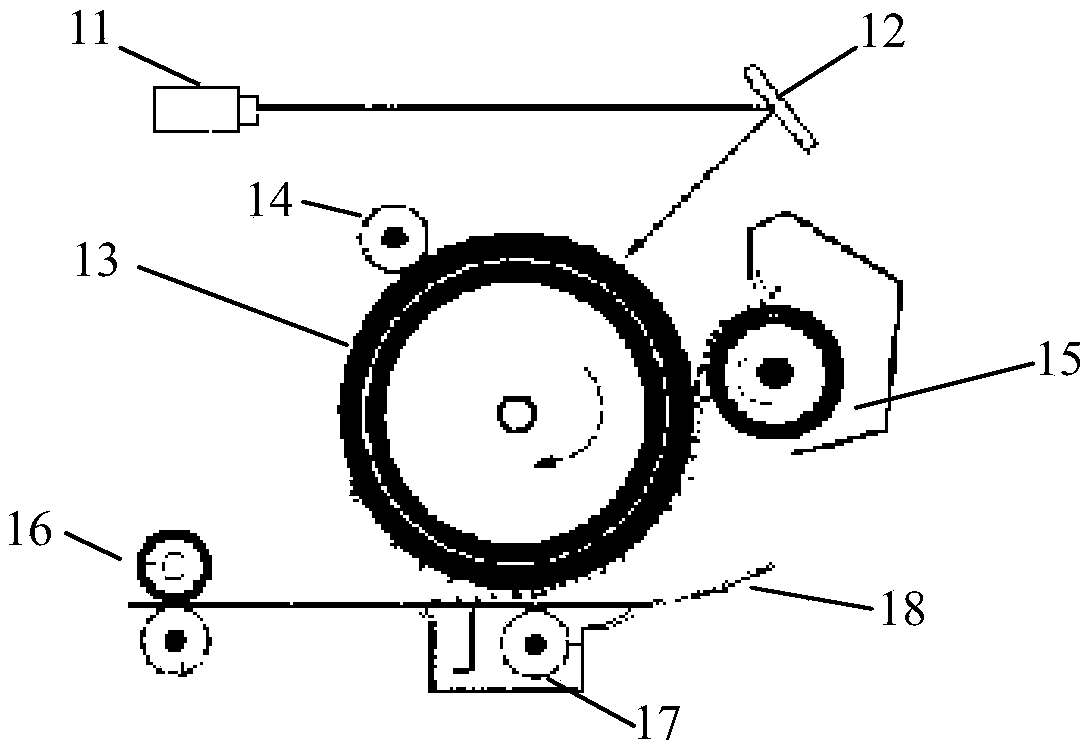
[0020] figure 1 A schematic diagram showing the working principle of a typical laser printer. Such as figure 1 As shown, the printer may include a laser 11 for emitting a laser beam; a mirror 12 for reflecting the laser beam to the photosensitive drum 13; a charging roller 14 for charging the printing roller 13; a developing roller 15; a pair of fixing rollers 16 (upper roller and lower roller); and transfer roller 17. After the printing paper 18 passes through the transfer roller 17, it is conveyed to a pair of fixing rollers 16. The fixing roller 16 is provided with a heating lamp (not shown). apart from figure 1 In addition to the components shown in the printer, the printer may also include other known components, such as a paper box, a paper feeding mechanism, and so on.

[0021] The printer may also include a control system, such as a controller, data interface, display, etc.

[0022] Since the printer needs to heat the printing paper during the printing process, when the ...

Embodiment 2

[0036] In addition to cooling by the printer control method in Embodiment 1, the temperature can also be lowered in other ways. Figure 4 Shows a schematic structural diagram of a printer according to an embodiment of the present invention. Such as Figure 4 As mentioned, in addition to the components that can be found in a typical printer, the printer may also include a ventilation device located in the paper output area of ​​the printer. The ventilation device may include at least one air outlet 41 on the inner side of the paper output area of ​​the printer and an air blowing device located inside the main body of the printer. The air blowing device may include, but is not limited to, a fan, an air pump, and the like. In an example, the shape of the air outlet 41 may be a slot on at least one side inside the paper outlet area. In another example, the shape of the air outlet 41 may be a plurality of air outlet holes on at least one side of the inner side of the paper discha...


PUM


Abstract

The invention relates to the field of printers, and discloses a control method for a printer. The control method is characterized in that the control method comprises the steps that a printing task isreceived; the received printing task is analyzed to obtain the workload of the printing task; whether the workload is greater than a set threshold or not is judged; under the situation that it is judged that the workload is greater than the set threshold value, a mapping table between the workload and the printing speed is called; and the printing speed is controlled according to the mapping table and the workload.

Description

Technical field [0001] The invention relates to a control method for a printer. Background technique [0002] The printer is one of the output devices of the computer and is used to print the computer processing results on the relevant media. There are three indicators to measure the quality of a printer: printing resolution, printing speed and noise. There are many types of printers. According to whether the printing element strikes the paper or not, they are divided into impact printers and non-impact printers. According to the structure of printing characters, it can be divided into full-form printers and dot matrix printers. According to the way that a line of characters is formed on paper, it is divided into a serial printer and a line printer. According to the technology used, it can be divided into cylindrical, spherical, inkjet, thermal, laser, electrostatic, magnetic, and LED printers. However, the current commonly used printers will encounter various problems in act...

Claims


Application Information

Patent Timeline
IPC IPC(8): B41J29/393
CPCB41J29/393
Inventor 张永涛
Owner 阜阳市易邦办公设备销售有限公司
Why Eureka
Try Eureka