Thread stand of sewing machine

A sewing machine and thread stand technology, which is applied to sewing machine components, sewing equipment, bobbin insertion rod components, etc., can solve the problem that the current people's requirements for the product cannot be met, the sewing coils cannot be placed at will, and the height of the thread stand cannot be adjusted. problem, to achieve the effect of simple structure, increased stability, and increased friction

Inactive Publication Date: 2018-11-09
SUZHOU KAICHENG SEWING EQUIP
View PDF0 Cites 2 Cited by
  • Summary
  • Abstract
  • Description
  • Claims
  • Application Information

AI Technical Summary

Problems solved by technology

[0002] A sewing machine is a machine that uses one or more sewing threads to form one or more stitches on the sewing material to interweave or sew one or more layers of sewing materials. It can sew cotton, hemp, silk, wool, Man-made fibers and other fabrics and leather, plastic, paper and other products, the stitches are neat and beautiful, smooth and firm, the sewing speed is fast, and it is easy to use, and the sewing thread is an important factor connecting such products. In order to facilitate the sewing thread on the sewing machine In use, the sewing machine is fixedly provided with a thread frame for fixing the sewing coil at a specific position. On the one hand, the thread frame of this sewing machine is not convenient for the random placement of the sewing coil, and the overall height of the thread frame cannot be adjusted, and on the other hand , only one sewing machine coil can be used at a time, and the flexibility is not high, which is far from meeting the current people's requirements for this product. Therefore, how to design a sewing machine thread frame has become a problem we need to solve at present

Method used


Image

  • Thread stand of sewing machine
  • Thread stand of sewing machine
  • Thread stand of sewing machine

Examples


Embodiment Construction

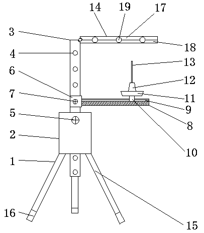
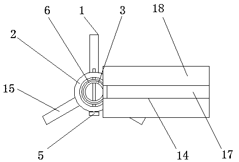
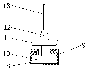
[0016] The present invention will be further described below in conjunction with specific embodiments, wherein, the accompanying drawings are only for exemplary illustrations, and what is shown is only a schematic diagram, rather than a physical map, and cannot be understood as a limitation to this patent. In order to better illustrate the present invention Specific embodiments, some parts in the drawings will be omitted, enlarged or reduced, and do not represent the size of the actual product. For those skilled in the art, it is understandable that some known structures and their descriptions in the drawings may be omitted. Based on The specific implementation modes in the present invention and all other specific implementation modes obtained by persons of ordinary skill in the art without making creative efforts all belong to the protection scope of the present invention.

[0017] see Figure 1-Figure 3 , the present invention provides a technical solution: a thread stand fo...


PUM


Abstract

The invention discloses a thread stand of a sewing machine. The thread stand comprises a triangular support frame, wherein a casing pipe is welded to the top of the triangular support frame, the innerside of the casing pipe is sleeved with a height adjusting rod in a sliding manner, adjusting holes are formed in the side surface of the height adjusting rod in an equal interval manner, a first fixed bolt is connected to the outer side of the casing pipe in a penetration manner and is connected into the adjusting holes in a penetration manner; the outer side of the height adjusting rod is sleeved with a sliding block in a sliding manner, the sliding block is located above the casing pipe, and the outer side of the sliding block is connected into the adjusting holes in a penetration manner through a second fixed bolt. The thread stand is provided with the adjusting holes, so that the interval between a placement board and a thread clamping row can be adjusted at will; the integral heightof the thread stand can be adjusted, so that the thread stand can be applicable to the sewing machines with different heights; and a plurality of coil trays can be mounted on the placement board once, so that the multiple sewing machines can be simultaneously used, and the thread stand is strong in flexibility and simple in structure and has wide application prospects.

Description

technical field [0001] The invention relates to the technical field of sewing machine accessories, in particular to a thread frame of a sewing machine. Background technique [0002] A sewing machine is a machine that uses one or more sewing threads to form one or more stitches on the sewing material to interweave or sew one or more layers of sewing materials. It can sew cotton, hemp, silk, wool, Man-made fibers and other fabrics and leather, plastic, paper and other products, the stitches are neat and beautiful, smooth and firm, the sewing speed is fast, and it is easy to use, and the sewing thread is an important factor connecting such products. In order to facilitate the sewing thread on the sewing machine In use, the sewing machine is fixedly provided with a thread frame for fixing the sewing coil at a specific position. On the one hand, the thread frame of this sewing machine is not convenient for the random placement of the sewing coil, and the overall height of the thr...

Claims


Application Information

Patent Timeline
Patent Type & Authority Applications(China)
IPC IPC(8): D05B43/00
CPCD05B43/00
Inventor 季锴
Owner SUZHOU KAICHENG SEWING EQUIP
Why Eureka
Try Eureka