Wall brick height support regulator

A technology of adjuster and height, which is applied in the direction of construction and building construction, can solve the problems of inconvenient rotation of nuts, low efficiency, inconvenient operation, etc., and achieve the effect of overcoming the inconvenience of adjustment

Pending Publication Date: 2018-11-09
JIAXING YONGBANG ELECTROMECHANICAL CO LTD
View PDF1 Cites 0 Cited by
  • Summary
  • Abstract
  • Description
  • Claims
  • Application Information

AI Technical Summary

Problems solved by technology

[0003] The notification number is CN204728665U and the Chinese patent titled "Tile Frame Height Adjuster" adopts threads as a height adjustment method, but this patent has limitations in use: one is when the height of the support is adjusted by rotating the nut, the nut The friction force between the upper end surface and the lower end surface of the support piece is too large, and the gravity of the wall brick pressed by the retaining piece finally falls on the contact between the two end surfaces, which makes the nut rotation inconvenient; this scheme has to overcome the relatively large nut rotation. Due to the large friction force, only tools can be used to rotate the nut; at the same time, one side of the nut is close to the wall, and when using a wrench to rotate it, it cannot be rotated for a full circle. In addition to the thickness of the human hand, usually the wrench has to be taken out and inserted into the nut after turning about 130 degrees. Then rotate and adjust, the adjustment efficiency is low, and the operation is inconvenient
When this solution is adjusted, the screw rod must be kept still. In this solution, the screw rod and the retaining member are not fixed. If only the wrench is used to rotate the nut, the phenomenon that the screw rod rotates at the same time will occur, which increases the difficulty of adjustment.

Method used


Image

  • Wall brick height support regulator

Examples


Embodiment 1

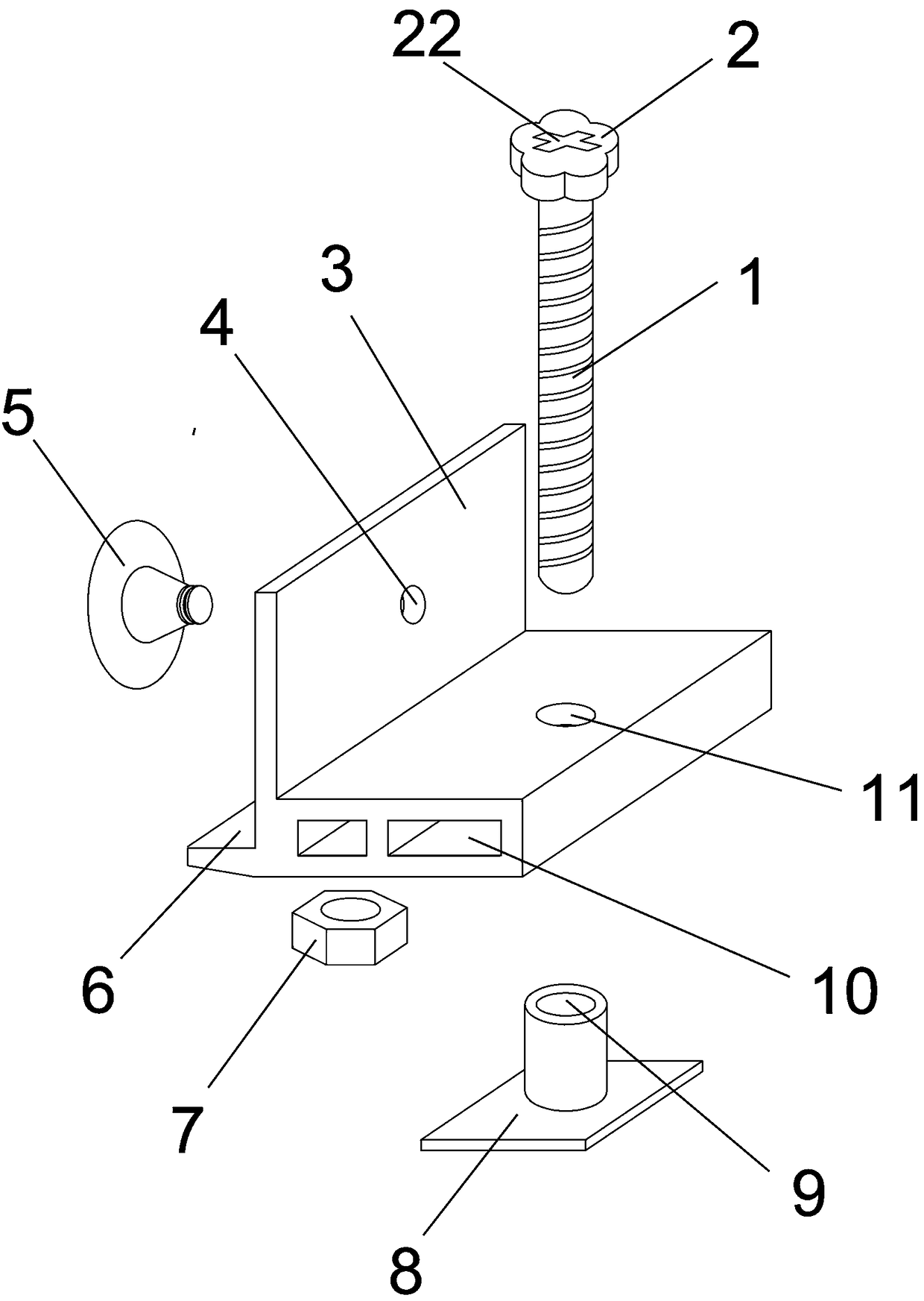
[0022] With reference to the accompanying drawings, the wall brick height support regulator includes a support member, the middle part of the support member is provided with a vertically upward backing plate 3, and the side of the support member against the wall is provided with a support plate 6 perpendicular to the backing plate. A through groove 10 is opened on the side, and a through hole 11 is provided vertically to allow the screw to pass through. The direction of the through groove is consistent with the length direction of the support. The nut is stuck in the through groove, and the center of the nut 7 coincides with the center of the through hole 11. The screw 1 with the handle 2 on the upper end is threadedly matched with the nut and penetrates the support, the distance between the center of rotation of the screw and the backing of the support is greater than 2 cm; a suction cup 4 is fixed on the backing of the side of the support against the wall; a base is provided ...

Embodiment 2

[0029] Different from the first embodiment, the present embodiment is provided with a cross slot 22 on the upper surface of the screw rod to match with the head of a Phillips screwdriver. The height of the support is adjusted by touching the screwdriver into the cross slot on the upper end surface of the screw rod for rotation, and the screwdriver rotation adjustment is also more convenient and efficient.


PUM


Abstract

The invention relates to a wall brick height support regulator. The regulator comprises a support member, wherein a vertically upward backup plate is arranged in the middle of the support member, a support plate vertical to the backup plate is arranged on the side, propped against the wall, of the support member, a nut is fixed on the back wall side of the support member, a screw provided with a handle at the upper end is in threaded fit with the nut and penetrates the support member, and the lower end of the screw is used for abutting against the ground. The lower part of a wall brick is supported by the support member, the height of the support member is adjusted by rotating the screw, a base can be kept still, the whole regulator cannot be moved easily, and accordingly, height of the base wall brick can be regulated, and the problem of inconvenience in adjustment by nuts in the prior art is solved.

Description

technical field [0001] The invention relates to an appliance for building decoration engineering, in particular to a base wall brick support and height adjustment device when wall bricks are pasted. Background technique [0002] For the laying of wall bricks, the position must be fixed under the base wall bricks with supports so that the height of the bottom wall bricks remains consistent, and then the wall bricks can be pasted up to keep the wall bricks in order. [0003] The notification number is CN204728665U and the Chinese patent titled "Tile Frame Height Adjuster" adopts threads as a height adjustment method, but this patent has limitations in use: one is when the height of the support is adjusted by rotating the nut, the nut The friction force between the upper end surface and the lower end surface of the support piece is too large, and the gravity of the wall brick pressed by the retaining piece finally falls on the contact between the two end surfaces, which makes t...

Claims


Application Information

Patent Timeline
Patent Type & Authority Applications(China)
IPC IPC(8): E04F21/18
CPCE04F21/18E04F21/1838E04F21/1894
Inventor 沈永根
Owner JIAXING YONGBANG ELECTROMECHANICAL CO LTD
Why Eureka
Try Eureka