Continuous pitching device

A ball-throwing device and ball-storing technology, which is applied in wellbore/well valve device, production fluid, wellbore/well components, etc., can solve the problems of inconvenient operation and low work efficiency, and achieve increased safety and construction efficiency. , the effect of simple structure

Active Publication Date: 2018-11-09
SINOPEC SSC +1
View PDF7 Cites 4 Cited by
  • Summary
  • Abstract
  • Description
  • Claims
  • Application Information

AI Technical Summary

Problems solved by technology

[0003] The purpose of the present invention is to provide a continuous ball throwing device to solve the problem of low working efficiency and inconvenient operation of the ball throwing device in the prior art during fracturing construction

Method used


Image

  • Continuous pitching device
  • Continuous pitching device

Examples


Embodiment Construction

[0024] Embodiments of the present invention will be further described below in conjunction with the accompanying drawings.

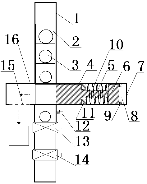
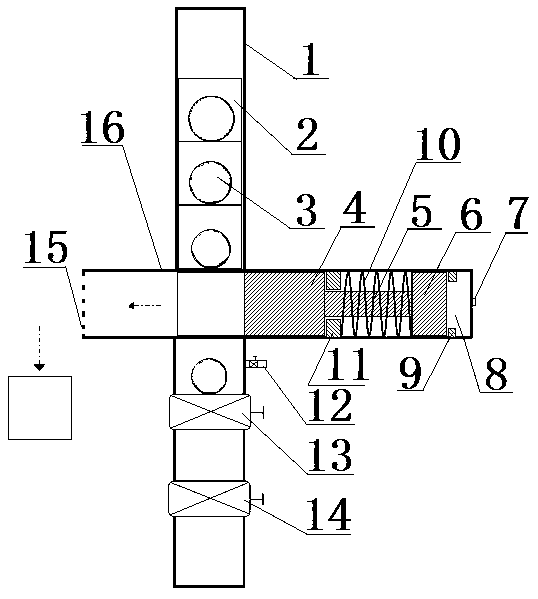
[0025] Embodiment 1 of the continuous pitching device of the present invention, as figure 1 As shown, the continuous ball-throwing device includes a ball-throwing pipeline 1, and a plurality of ball storage barrels 2 are continuously arranged up and down inside the ball-throwing pipeline 1, and the top of the ball storage barrel 2 has a supporting structure for supporting the fracturing ball 3. In this embodiment The top of the ball storage barrel 2 is closed to form the support structure, and the lower end of the ball storage barrel 2 is open. The ball storage pipe 1 is provided with a stop structure cooperating with the ball storage barrel 2 in the axial direction under a plurality of ball storage barrels 2. The stop structure is provided with an avoidance hole for avoiding the fracturing ball 3. The ball delivery pipe 1 An opening for the ball storag...


PUM


Abstract

The invention relates to a continuous pitching device. The continuous pitching device comprises a pitching pipeline which is internally provided with multiple ball storing barrels continuously, support structures used for supporting fracturing balls are arranged on the tops of the ball storing barrels, through holes allowing the fracturing balls to pass through are formed in the lower ends of theball storing barrels, stop structures which are in stop cooperation with the ball storing barrels in the axial direction are arranged on the portions, below the multiple ball storing barrels, in the pitching pipeline, avoidance holes avoiding the fracturing balls are formed in the portion where the stop structures are located, and an opening allowing the ball storing barrels to leave the pitchingpipeline is formed in the side wall of the pitching pipeline; the continuous pitching device further comprises a reciprocating pushing mechanism used for pushing the ball storing barrels out of the opening, the reciprocating pushing mechanism of the continuous pitching device can push the pushing the ball storing barrels away from the pitching pipeline in the reciprocating movement process, then continuous pitching of the fracturing balls can be achieved, continuity of construction is ensured, and the construction efficiency is improved; the phenomenon that constructors enter a high pressure area can be avoided, and the safety risks are lowered to the maximum extent.

Description

technical field [0001] The invention relates to a continuous ball throwing device. Background technique [0002] Since there are multiple oil reservoirs in the formation, each reservoir needs to be exploited in one or more stages, so staged fracturing is required, and a multi-stage ball-dropping staged fracturing construction technology is used. With the increase of fracturing technology, the number of fracturing balls that need to be released is gradually increasing. At present, during the implementation of the staged fracturing process, construction personnel need to enter the high-pressure area of ​​fracturing and deliver fracturing balls in the wheeled ball-dropping device to complete staged fracturing. However, the wellhead pressure during the construction process is very high, threatening The personal safety of the operator. However, most ball delivery devices can only throw one fracturing ball at a time. After each fracturing stage, construction personnel must enter...

Claims


Application Information

Patent Timeline
IPC IPC(8): E21B43/26E21B34/08
CPCE21B34/08E21B43/26
Inventor 蒋新立贾光亮马成云李晔旻温伟晁伟栋郑道明王群来
Owner SINOPEC SSC
Why Eureka
Try Eureka