Magnetic speed reducer for vehicle braking installed on driving shaft

A vehicle braking and decelerator technology, applied in the field of magnetic decelerators and magnetic decelerators for vehicle braking, can solve the problems of large consumption, high heating temperature of oil, easy deterioration, etc., to reduce pressure and avoid oil leakage. The effect of pollution

Active Publication Date: 2018-11-09
DALIAN JIAOTONG UNIVERSITY
View PDF18 Cites 4 Cited by
  • Summary
  • Abstract
  • Description
  • Claims
  • Application Information

AI Technical Summary

Problems solved by technology

However, the hydraulic reducer has the following application defects: 1. The oil that transmits power works in a high-temperature state for a long time, which is easy to deteriorate, age, and consumes a lot; 2. The working oil in the braking state is too hot and easy to vaporize, so it needs a lot of energy. 3. High temperature working liquid is easy to leak and cause environmental pollution

Method used


Image

  • Magnetic speed reducer for vehicle braking installed on driving shaft
  • Magnetic speed reducer for vehicle braking installed on driving shaft
  • Magnetic speed reducer for vehicle braking installed on driving shaft

Examples


Embodiment Construction

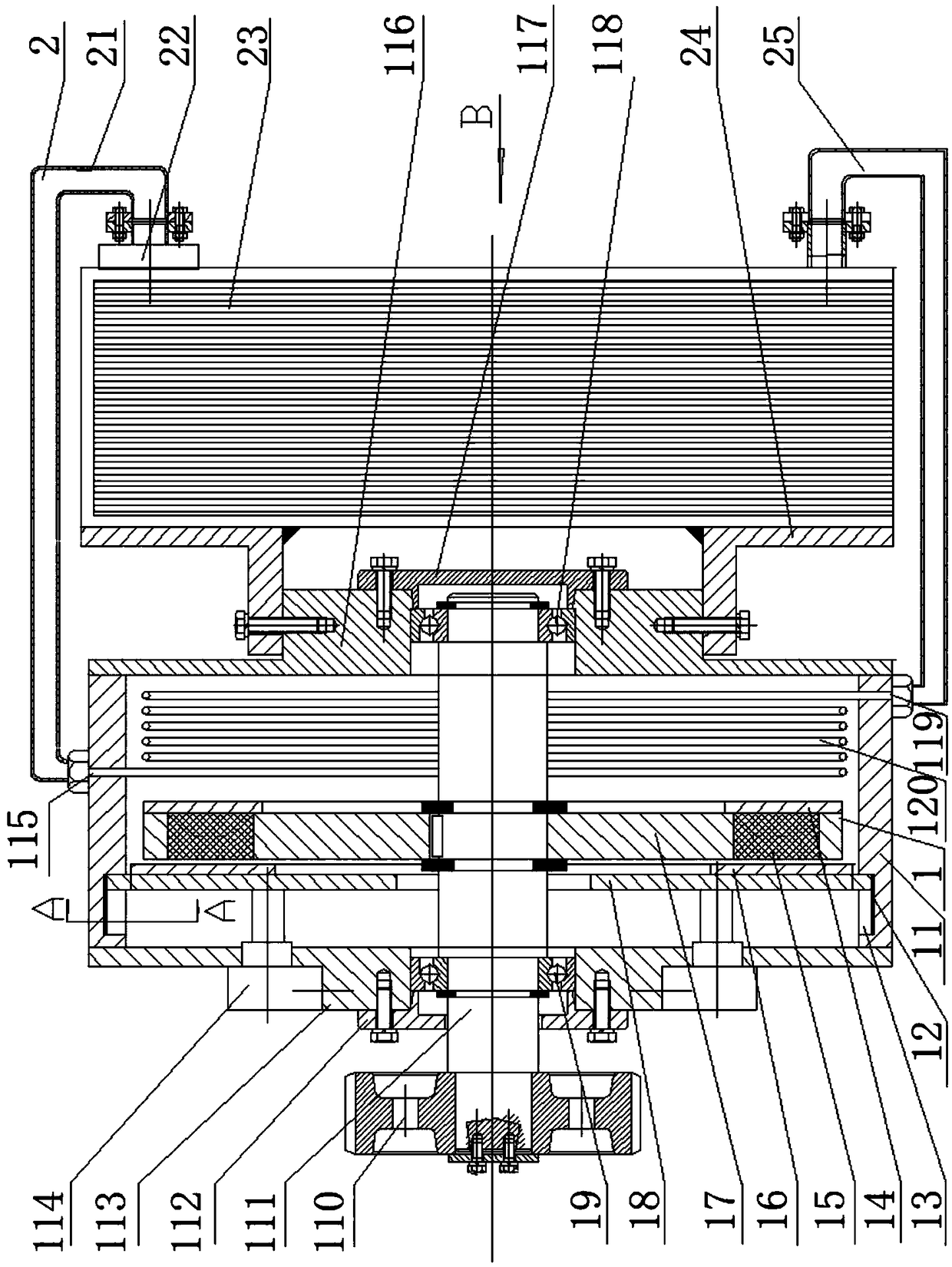
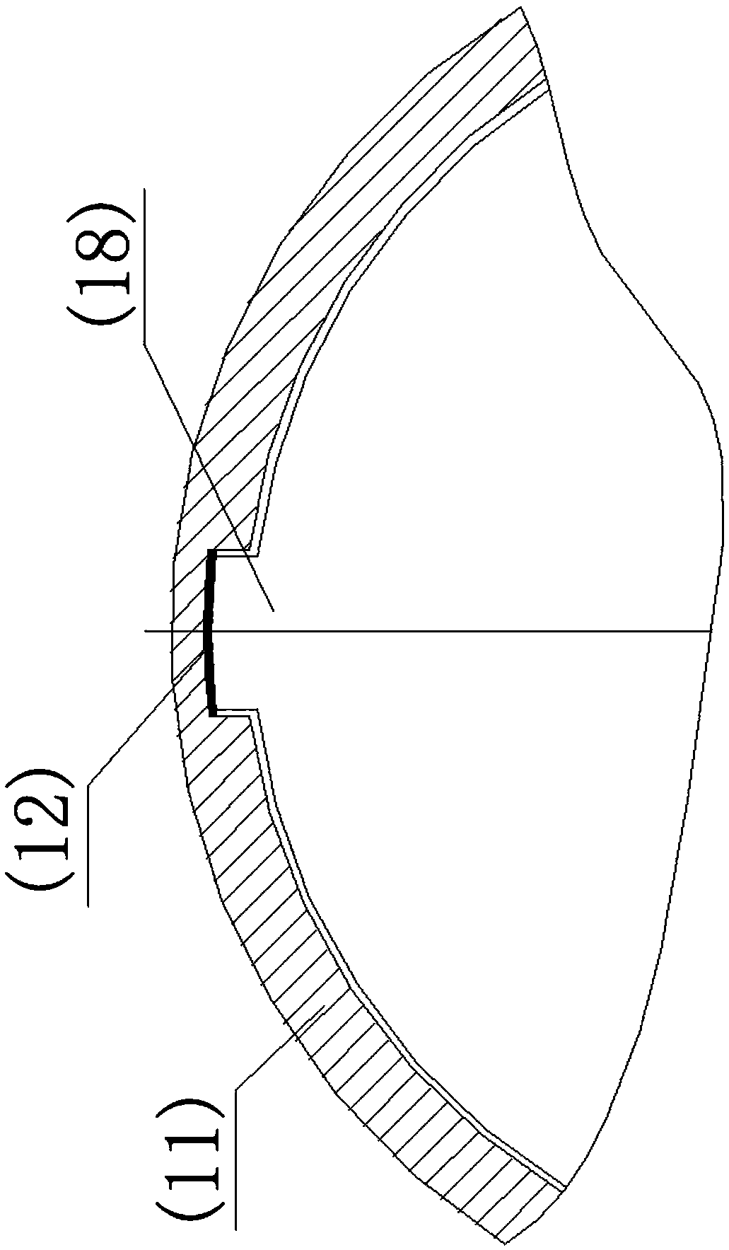
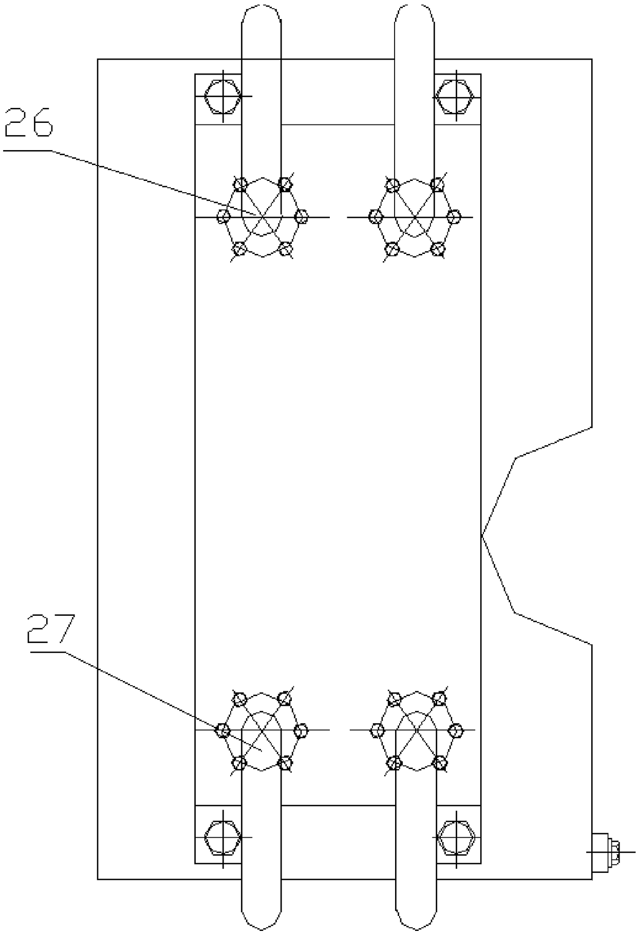
[0020] Such as figure 1 , figure 2 , image 3 , Figure 4 A magnetic speed reducer for vehicle braking shown on the drive shaft includes a magnetic speed reducer 1, a cooling system 2, a vehicle water tank 3, and a vehicle drive shaft gear 4. It is characterized in that the magnetic speed reducer 1 is composed of Connecting body 11, wear-resistant layer 12, chute 13, spacer disk 14, magnet 15, copper disk 16, disk body 17, copper disk body 18, bearing I19, speed-increasing gear 110, shaft 111, end cover I112, body frame Ⅰ113, reversing hydraulic cylinder 114, water inlet flange 115, body frame Ⅱ 116, end cover Ⅱ 117, bearing Ⅱ 118, return water flange 119, cooling water pipe 120, body frame Ⅰ 113, and body frame Ⅱ 116 pass through the connecting body 11 After forming an integrated frame, it is fastened on the bracket 24 installed on the car body. The speed-increasing gear 110 is installed on one end of the shaft 111. The shaft 111 is supported on the integrated frame by th...


PUM


Abstract

The invention relates to a magnetic speed reducer for vehicle braking installed on a driving shaft. A magnetic disk body is fixed on a shaft, magnets which are uniformly distributed in the circumferential direction are embedded in the shaft, a copper disc is installed on the inner face of the copper disc body, a pair of piston rods of a reversing hydraulic cylinder symmetrically installed on a body frame I are in a rigid connection with the outer side of the copper disc body, and a pair of protruding blocks are symmetrically extended in the radial direction and are correspondingly connected into sliding grooves of a connecting body in an inserted mode to carry out axial reciprocating sliding; a hydraulic oil inlet and outlet is changed, the reversing hydraulic cylinder is pushed reversely,and the piston rods pull the cooper disc body to change the distance between the copper disc and the magnets; the magnetic gap between the copper disc and the magnets is small when in braking, magnetic force is generated to enable vehicle wheels to decelerated and carried out breaking, a vehicle water tank pump is started to provide cooling water, and heat absorption is carried out through the cooling water passed through a heat exchanger; meanwhile, a pressure pump is started, the pumped water passes through a heat exchanger water outlet pipe and a water inlet flange opening to enter a cooling water pipe, heat generated during vibration is absorbed by the water, a high temperature water passes through a water return flange opening and a heat exchanger water return pipe and flows back tothe heat exchanger to release the heat; and when not braked, the copper disc and the magnets are at a safe distance, no magnetic force is generated, and the vehicle water tank pump and the pressure pump are closed. The magnetic speed reducer for the vehicle braking installed on the driving shaft has the advantages of being free of pollution and large in braking torque.

Description

technical field [0001] The technology of the invention mainly relates to a magnetic speed reducer, in particular to a magnetic speed reducer for vehicle braking installed on a drive shaft, which belongs to the technical field of magnetic transmission. Background technique [0002] In order to improve the safety performance of heavy-duty vehicles, improve their average driving speed and the reliability of the braking system, vehicles are often equipped with auxiliary braking systems to achieve high-speed deceleration and braking. The hydraulic retarder is one of the main components to achieve auxiliary braking. one. In foreign countries, the hydraulic reducer has been widely guaranteed. Especially in mountainous and hilly areas such as northern Europe, the western United States, and Japan, many buses, engineering vehicles, and heavy-duty transport vehicles are equipped with hydraulic reducers. The design and development of the reducer has formed a complete set of advanced t...

Claims


Application Information

Patent Timeline
IPC IPC(8): F16D63/00F16D65/78B60T1/06B61H11/00
CPCB60T1/062B61H11/00F16D63/002F16D65/78F16D2065/783F16D2065/787
Inventor 邵万珍吴岳卢洪超李邵颖
Owner DALIAN JIAOTONG UNIVERSITY
Why Eureka
Try Eureka