Novel heat-pipe-type vacuum glass pipe heat collector

A vacuum glass tube and heat pipe type technology, which is applied to solar collectors, solar collector safety, solar collector components, etc., can solve problems such as freezing cracks, system water leakage, system collapse, etc., and reduce local Effects of resistance, ensuring flexibility, and ensuring safety

Pending Publication Date: 2018-11-09
INST OF ENGINEERING THERMOPHYSICS - CHINESE ACAD OF SCI +1
View PDF0 Cites 1 Cited by
  • Summary
  • Abstract
  • Description
  • Claims
  • Application Information

AI Technical Summary

Problems solved by technology

[0005] Existing vacuum glass tube solar collectors operate in winter, especially in extremely cold weather. If water is used as the heat transfer medium for energy absorption, when there is water in the glass tube, there will be a danger of freezing and cracking; if Drain the water, and when water is applied again, due to the rapid heating of the glass tube, the high temperature of the inner wall of the glass tube and the low temperature of the cold water will appear, and there is a danger of the glass tube bursting; moreover, when building a large heat collection system, multiple solar collectors The heaters are connected in series and parallel to each other. Even if a vacuum glass tube breaks, it will cause water leakage in the entire system, resulting in system failure or paralysis.
[0006] (2) The effective utilization rate is not high
The operating efficiency of existing collectors is about 60%, and the effective utilization rate of solar energy is not high
[0008] (3) The traditional form of vacuum

Method used


Image

  • Novel heat-pipe-type vacuum glass pipe heat collector
  • Novel heat-pipe-type vacuum glass pipe heat collector
  • Novel heat-pipe-type vacuum glass pipe heat collector

Examples


Embodiment Construction

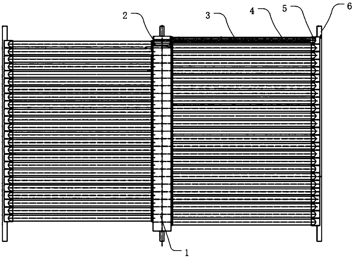
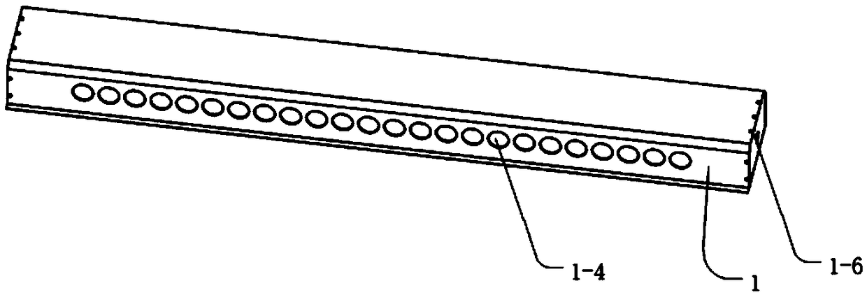
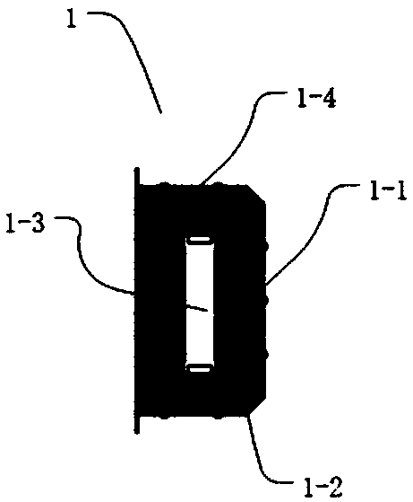
[0031] Figure 1 to Figure 6 It is a novel heat pipe type vacuum glass tube heat collector according to the present invention. The application will be described in detail below in conjunction with specific embodiments and accompanying drawings.

[0032] The examples described here are specific specific implementations of the present invention, and are used to illustrate the concept of the present invention. They are all explanatory and exemplary, and should not be construed as limiting the implementation of the present invention and the scope of the present invention. In addition to the embodiments described here, those skilled in the art can also adopt other obvious technical solutions based on the claims of the application and the contents disclosed in the description, and these technical solutions include adopting any obvious changes made to the embodiments described here. Replacement and modified technical solutions.

[0033] The accompanying drawings in this specificatio...


PUM


Abstract

The invention discloses a novel heat-pipe-type vacuum glass pipe heat collector comprising a header, heat transmitting devices and a vacuum glass pipe. The heat transmitting devices are arranged in the vacuum glass pipe, one end of the vacuum glass pipe is connected with a through hole in the side wall of the header, and the other end of the vacuum glass pipe is fixed to a tail holder of a support. The novel heat-pipe-type vacuum glass pipe heat collector is characterized in that the header is arranged vertically, the heat transmitting devices are symmetrically distributed on the two sides ofthe header and skew horizontally upwards by a certain degree. According to the heat-pipe-type vacuum glass pipe heat collector, the structure is reasonable, the heat transmitting devices are arrangedhorizontally upwards, under the effect of gravity force, heat transmitting media in the heat transmitting devices are evaporated and condensed and flow back, circular reciprocating is conducted, and heat exchange is achieved. Owing to isolation of the water media in the header and the vacuum glass pipe, the problem that the vacuum glass pipe is frozen to be cracked under the extremely cold weatheris solved, and the using safety is ensured. The quantity of water running in the header is small, the local resistance is effectively reduced, and the flexibility of setting up of a large heat collection system is ensured.

Description

technical field [0001] The invention relates to a tube type heat collector, in particular to a novel heat pipe type vacuum glass tube heat collector. Background technique [0002] The vacuum tube collector is a new type of solar heat collector developed on the basis of the flat plate collector. The interlayer between the heat absorber and the glass tube maintains a high vacuum. The core component of this collector is a vacuum tube, which is mainly composed of an inner heat absorber and an outer glass tube. The vacuum tube collector can effectively suppress the conduction and convection heat loss of the air in the vacuum tube, and because the selective absorbing coating has low infrared emissivity, it can significantly reduce the radiation heat loss of the heat absorbing plate. Vacuum tube collectors are mainly divided into all-glass vacuum tube collectors and heat pipe vacuum tube collectors. [0003] The existing vacuum tube collectors have the following problems: [000...

Claims


Application Information

Patent Timeline
IPC IPC(8): F24S10/95F24S70/12F24S80/30F24S40/70
CPCY02E10/44Y02B10/20
Inventor 袁达忠
Owner INST OF ENGINEERING THERMOPHYSICS - CHINESE ACAD OF SCI
Why Eureka
Try Eureka