Coupling method for light emitter and light emitter

An optical transmitter and laser technology, applied in the field of optical communication, can solve the problems of optical power drop, difficulty in repairing, etc., and achieve the effects of reducing production costs, saving coupling time, and avoiding complicated steps

Inactive Publication Date: 2018-11-09
HISENSE BROADBAND MULTIMEDIA TECH
View PDF4 Cites 14 Cited by
  • Summary
  • Abstract
  • Description
  • Claims
  • Application Information

AI Technical Summary

Problems solved by technology

[0003] With regard to the above-mentioned existing assembly method of the optical transmitter, the inventors of the present invention found that: in the prior art, after the laser, the optical multiplexing component and the collimator lens are fixed, the optical fiber adapter is coupled and fixed in an active way , so during

Method used


Image

  • Coupling method for light emitter and light emitter
  • Coupling method for light emitter and light emitter
  • Coupling method for light emitter and light emitter

Examples


Embodiment 1

[0024] Based on the structure of the above optical transmitter, the embodiment of the present invention provides a coupling method of the optical transmitter, such as Figure 5 shown, including:

[0025] S501. Fix N lasers, optical multiplexing components, shifting prisms, and fiber optic adapters at designated positions.

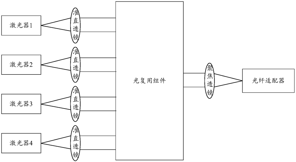
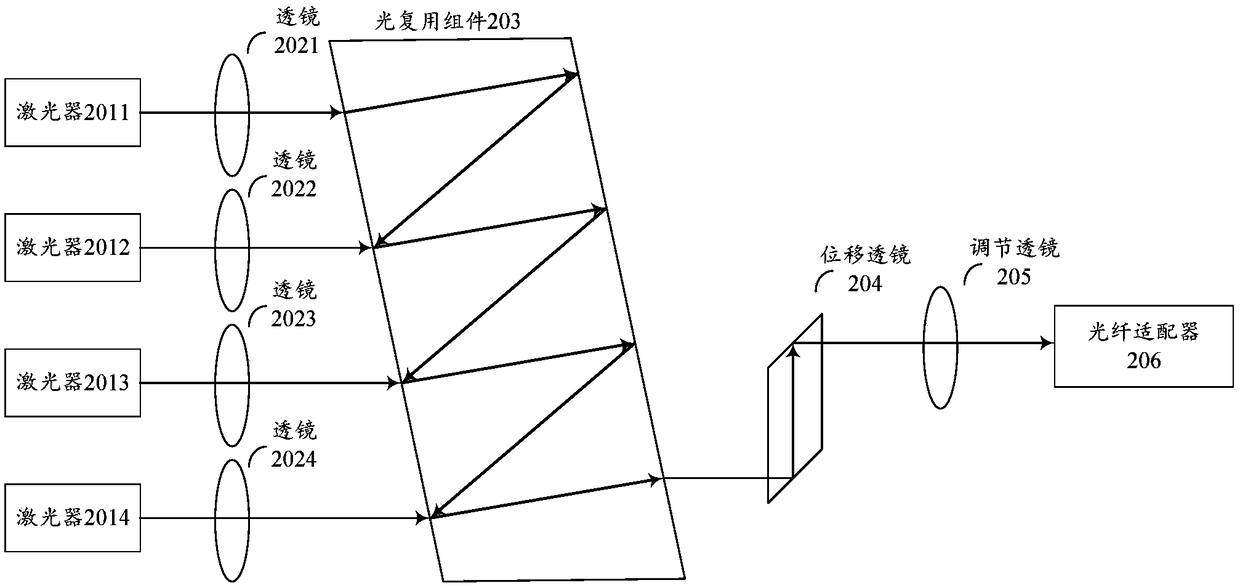
[0026] Exemplary, with figure 2The optical transmitter shown is taken as an example. First, the four lasers 2011-2014, the optical multiplexing component 203, the displacement prism 204, and the fiber adapter 206 are fixed at designated positions.

[0027] Wherein the fiber optic adapter may be a fiber optic adapter with an isolator.

[0028] S502. Determine the position of the first lens 2021 corresponding to the first laser 2011 according to the optical power received by the optical fiber adapter 206 when the first laser 2011 is in a light-emitting state.

[0029] Specifically, the first lens 2021 corresponding to the first laser 2011 is a collimating...

Embodiment 2

[0057] In another embodiment, the embodiment of the present invention also provides an optical transmitter, which is assembled using the coupling method provided in the first embodiment above, and the structure and optical path principle of the optical transmitter can be referred to above figure 2 The structure and principle of the optical path of the provided optical transmitter will not be repeated here.


PUM


Abstract

The embodiment of the invention provides a coupling method for a light emitter and the light emitter, and relates to the technical field of optical communication. According to the coupling method forthe light emitter and the light emitter, the coupling process of the light emitter can be simplified, the coupling time can be saved, and the production cost can be lowered. The method comprises the following steps of carrying out passive fixation on a laser, an optical multiplexing component and an optical fiber adapter firstly and then adjusting the positions of a first lens and a second lens inan active environment so as to complete coupling assembly of the light emitter. The method is applied to production and assembly of the light emitter.

Description

technical field [0001] The invention relates to the technical field of optical communication, in particular to a coupling method and assembly equipment of an optical transmitter. Background technique [0002] In the field of high-speed data communication, the technology of micro-optics assembly is more and more widely used. Such as figure 1 It is a schematic structural diagram of a typical multiplexed optical transmitter, in which the optical transmitter mainly includes 4 lasers, 4 collimating lenses, an optical multiplexing component that combines 4 channels of light into 1 channel of light, a focusing lens, a Fiber optic adapter, in which 4 lasers can emit laser light with different wavelengths. The basic working principle of the optical transmitter is: 4 lasers emit 4 different wavelengths of light, which become 4 parallel collimated lights through 4 collimating lenses, and 4 parallel collimated lights are synthesized by an optical multiplexing component 1 way of light...

Claims


Application Information

Patent Timeline
IPC IPC(8): G02B6/42
CPCG02B6/4206G02B6/4214G02B6/4225
Inventor 杜光超唐永正
Owner HISENSE BROADBAND MULTIMEDIA TECH
Why Eureka
Try Eureka