Multi-path parallel optical signal transmission module

A technology for transmitting modules and optical signals, which is applied in the field of optical modules to achieve the effects of improving yield, improving transmission performance, and simplifying coupling and testing processes

Pending Publication Date: 2021-08-10
尚宁光电无锡有限公司
View PDF0 Cites 0 Cited by
  • Summary
  • Abstract
  • Description
  • Claims
  • Application Information

AI Technical Summary

Problems solved by technology

However, in many occasions of industrial Internet or power control, a large number of signals need to be transmitted in a limited space, and the solution of optical fiber terminal can only provide 1-to-1 single-channel transmission. Transmitting and receiving optical fiber terminals and optical fibers to realize transmission
This has caused many adverse effects on system complexity, volume, power consumption, etc.

Method used


Image

  • Multi-path parallel optical signal transmission module
  • Multi-path parallel optical signal transmission module
  • Multi-path parallel optical signal transmission module

Examples


Embodiment Construction

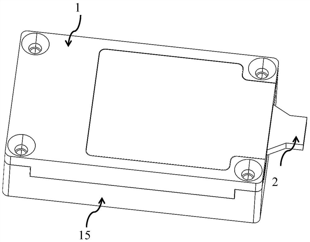
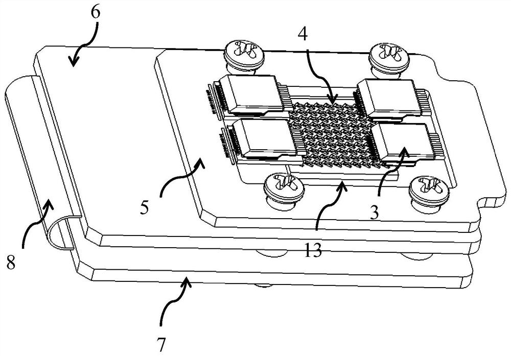
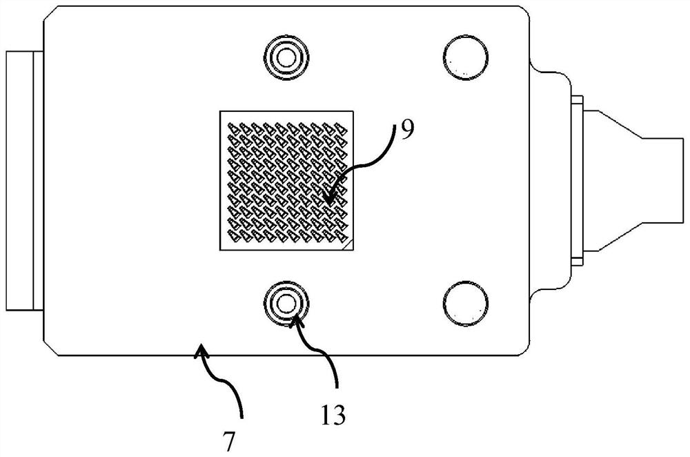
[0022] Combine below Figure 1 to Figure 7 The present invention will be further described.

[0023] A multi-channel parallel optical signal transmission module includes an optical transmission component, a circuit board, a flexible board, and a connector; in order to realize signal transmission, the signal transmission of the optical transmission component is realized by setting the circuit board. The circuit board includes a first circuit board 6 and a second circuit board 7. In order to save the space occupied by the circuit board and enable communication between the circuit boards, the first circuit board 6 and the second circuit board 7 are arranged vertically and symmetrically up and down. And connected through a flexible board 8. In order to separate the optical transmission component from the circuit part and make it into an independent optical transmission component, which greatly simplifies the coupling and testing process of the light emitting component and effecti...


PUM


Abstract

The invention discloses a multi-path parallel optical signal transmission module, and belongs to the field of optical modules. The multi-path parallel optical signal transmission module comprises an optical transmission assembly, circuit boards, a flexible board and a connector. The circuit boards comprise a first circuit board and a second circuit board, and the first circuit board and the second circuit board are vertically and symmetrically arranged along a vertical direction and are connected through the flexible board; a bonding pad is arranged on the first circuit board, and the connector is connected with the bonding pad; the first circuit board is provided with a substrate, the optical transmission assembly is arranged on the substrate, the substrate is provided with a connecting contact, and the connector is connected with the connecting contact. According to the multi-path parallel optical signal transmission module, the flexible board is connected to the two circuit boards, so that the size of the module is reduced, and a more complicated circuit is realized in a smaller space. The micro contact connector is adopted, so that I / O electrical connection with higher density is realized. The optical transmission assembly is separated from the circuit part and is made into an independent optical transmitting or receiving assembly, so that the coupling and testing process of the optical transmitting assembly can be greatly simplified, and the yield is effectively improved.

Description

technical field [0001] The invention relates to the field of optical modules, in particular to a multi-channel parallel optical signal transmission module. Background technique [0002] In industrial Internet and power network control, a large number of control or sensing signals need to be transmitted. In order to reduce system interference, optimize signal transmission quality, and extend signal transmission distance, optical fibers are used in many cases instead of cables to transmit signals. However, the format of such signals is usually a signal without "0" and "1" balance encoding, or even a DC control signal. This signal format is not suitable for conventional photoelectric conversion modules (requires DC balance coding), so AVAGO or Toshiba is usually used to design and develop a fiber optic terminal module for low-speed signal transmission to solve the above problems. This fiber optic terminal module For: HFBR1444 single transmitter module + HFBR2412 single receive...

Claims


Application Information

Patent Timeline
Patent Type & Authority Applications(China)
IPC IPC(8): G02B6/42
CPCG02B6/4246G02B6/4256G02B6/428
Inventor 孙全意周四海齐鹏远
Owner 尚宁光电无锡有限公司
Why Eureka
Try Eureka