Filter and method for generating resonant mode and equivalent capacitance
What is AI technical title?
AI technical title is built by Patsnap AI team. It summarizes the technical point description of the patent document.
A resonant mode and filter technology, applied in the field of effective capacitors, can solve the problems of high weight and cost, large filter size, etc.
Inactive Publication Date: 2018-11-09
深圳市永盛微波技术有限公司
View PDF2 Cites 3 Cited by
Summary
Abstract
Description
Claims
Application Information
AI Technical Summary
This helps you quickly interpret patents by identifying the three key elements:
Problems solved by technology
Method used
Benefits of technology
Problems solved by technology
[0003] The purpose of the invention is to solve the technical problems of large filter size, high weight and cost
Method used
Image
Click on the blue label to locate the original text in one second.
Reading with bidirectional positioning of images and text.
Examples
Embodiment 2
[0155] Figure 5 A flowchart of a method for generating a resonance mode for a filter (that is, a filter module or a resonant cavity in a filter module) in an embodiment of the present invention, the method includes steps:
[0156] S101, obtaining an equivalent structure of the resonant cavity;
[0157] The equivalent structure refers to an effect diagram simulating the structure of the resonant cavity;
[0158] The equivalent structure diagram is as Figure 5 shown;
[0159] S102. Perform odd and even mode resonance analysis on the equivalent structure to obtain an odd and even mode resonance structure of the resonator;
[0160] The odd-even mode resonance analysis is a commonly used analysis method in microwave circuit structures, which is common knowledge and will not be described in detail;
[0161] After carrying out odd and even mode resonance analysis, obtain the odd and even mode resonant structure of described resonant cavity, as Figure 6 shown;
[0162] pass ...
Embodiment 3
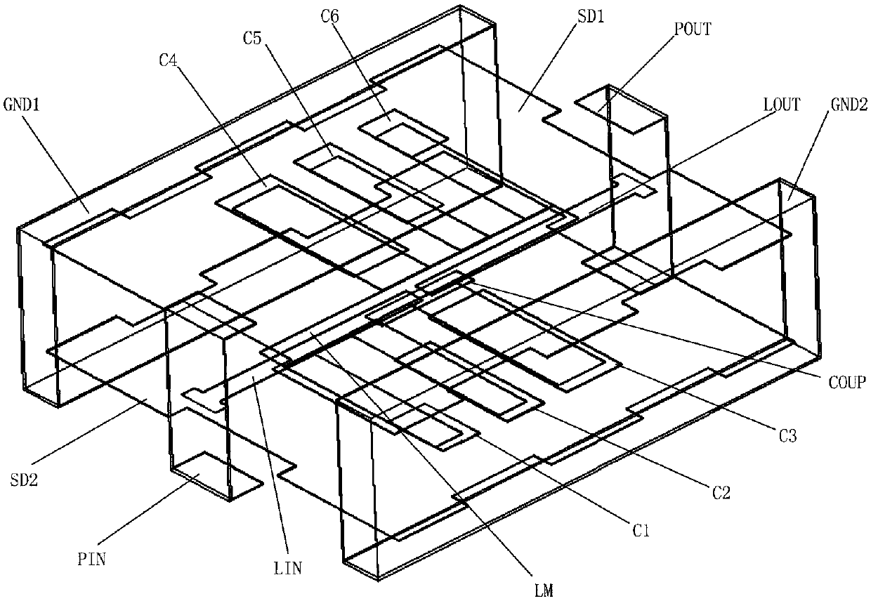
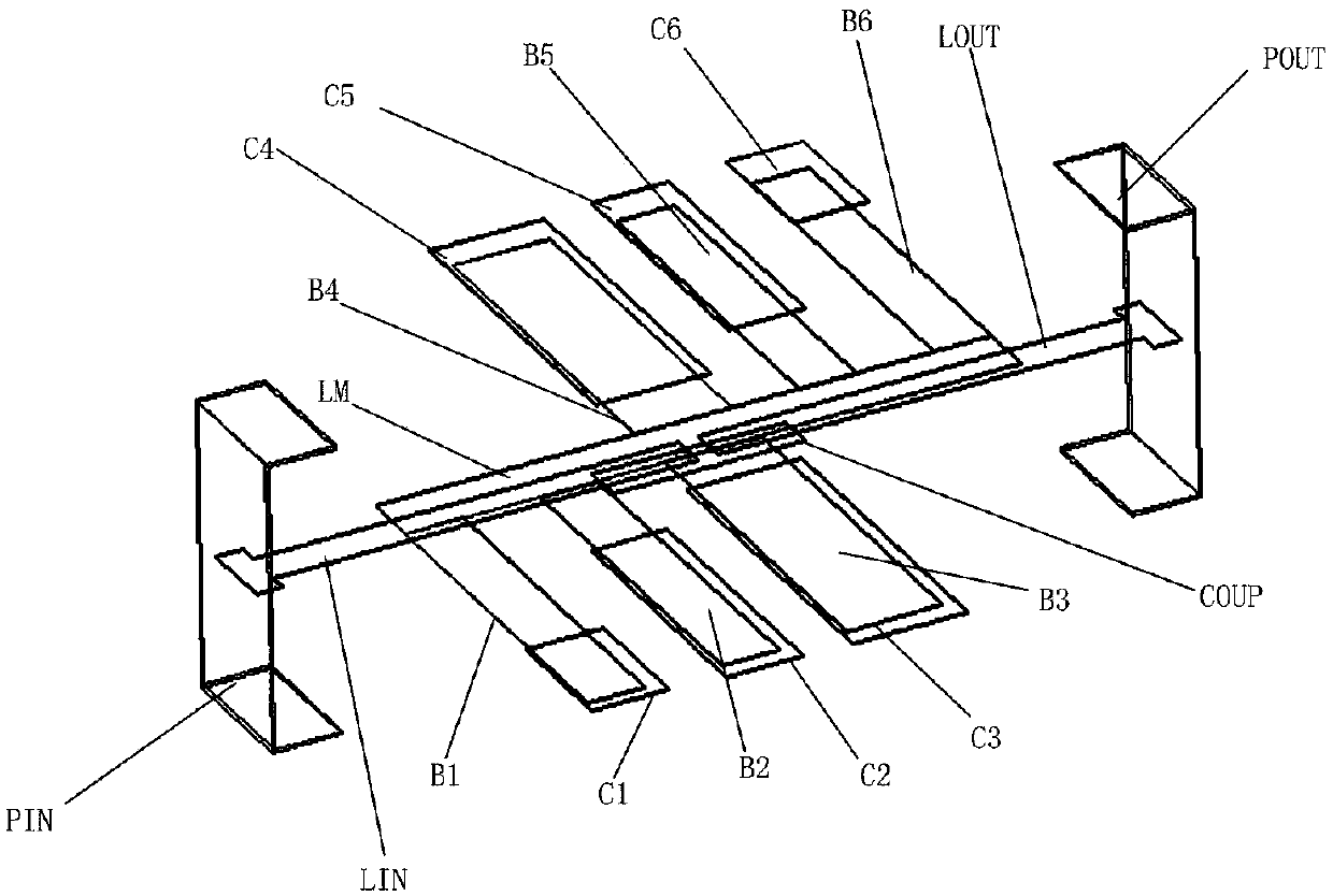
[0239] The resonant cavity of the filter module is in the equivalent structure diagram (such as Figure 7 , Figure 8 , Figure 9 Shown) on the basis of adding grounding equivalent capacitance at the open end of each branch; the equivalent capacitance is composed of B1 and C1, B2 and C2, B3 and C3, B4 and C4, B5 and C5, B6 and C6 respectively, A total of six, by connecting the ground equivalent capacitance to the resonant stub to replace the open-circuit stub;
[0240] The principles of the six capacitors are the same, and only the capacitor composed of B1 and C1 is used as an example to illustrate its structural composition. The part of B1 that is not directly opposite to C1 is an open branch in the equivalent structure diagram, and the part that is directly opposite to B1 and C1 is a metal conductor. There is a medium between the conductors to form a capacitor structure; the end of C1 that is not directly opposite to B1 is connected to the ground layer GND2 to form a groun...
PUM
Abstract
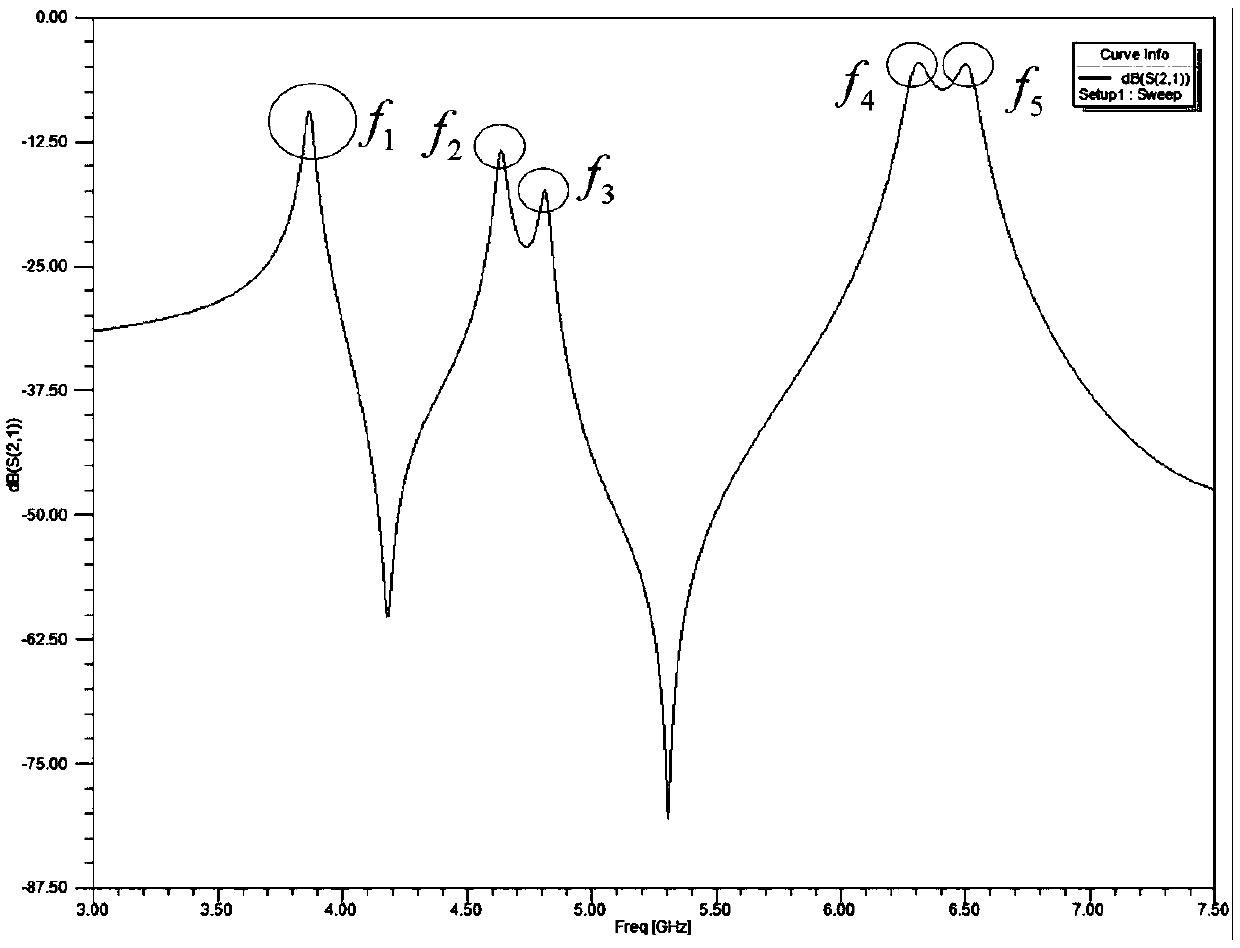
The present invention discloses a filter and a method for generating resonant mode and equivalent capacitance. The filter comprises an input port PIN, an output port POUT, a filter module having fiveresonant modes and two passbands, a ground line layer GND1, a ground line layer GND2, a shielding layer SD1 and a shielding layer SD2 which are respectively located at different horizontal planes andcommonly form a three-dimensional integration structure so as to effectively shorten the whole size and weight of the filter and reduce the cost; the flexible combination of the resonance stub and thecapacitance conduction band is employed to achieve five resonant modes, the structure is simple, the five resonant modes are flexibly achieved, and the flexibility is high; and the resonant frequencies of the five resonant modes are regulated to combine the neighboring resonant frequencies to achieve dual passband, and the echo loss of the input port is superior to 17dB, and the insertion loss inthe passbands is superior to 2.5dB.
Description
technical field [0001] The invention belongs to the field of microwave technology, in particular to a filter and a method for generating a resonant mode and an equivalent capacitance. Background technique [0002] A filter is a signal processing device whose main function is frequency-selective transmission of signals, retaining useful signals in a specific frequency range of the input signal in the output signal, and suppressing interference signals or useless signals of other frequencies. The diversification of wireless communication system applications puts forward the need to use only one communication terminal to complete multiple different types of services. Mapped in microwave communication circuits, this requires microwave devices to be able to work in several separate modes or frequency bands at the same time. In the previous RF microwave system, each communication frequency band required an independent RF front-end transceiver device to meet dual-frequency, multi-...
Claims
Application Information
Patent Timeline
Application Date:The date an application was filed.
Publication Date:The date a patent or application was officially published.
First Publication Date:The earliest publication date of a patent with the same application number.
Issue Date:Publication date of the patent grant document.
PCT Entry Date:The Entry date of PCT National Phase.
Estimated Expiry Date:The statutory expiry date of a patent right according to the Patent Law, and it is the longest term of protection that the patent right can achieve without the termination of the patent right due to other reasons(Term extension factor has been taken into account ).
Invalid Date:Actual expiry date is based on effective date or publication date of legal transaction data of invalid patent.

