Low profile broadband antenna

A broadband antenna, low profile technology, applied in antennas, resonant antennas, electrical short antennas, etc., can solve the problems of large ground plate size and unfavorable antenna miniaturization, and achieve the effect of small size, good matching and easy integration

Inactive Publication Date: 2018-11-09
HARBIN ENG UNIV
View PDF6 Cites 5 Cited by
  • Summary
  • Abstract
  • Description
  • Claims
  • Application Information

AI Technical Summary

Problems solved by technology

The feeder is located on the dielectric substrate, while the dipole and the ground plane are located on the back of the dielectric substrate. This antenna has good bandwidth performance and good directivity, but the size of the ground plate is large, which is not conducive to the miniaturization of the antenna.

Method used


Image

  • Low profile broadband antenna
  • Low profile broadband antenna
  • Low profile broadband antenna

Examples


Embodiment 1

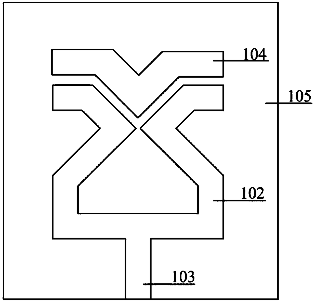
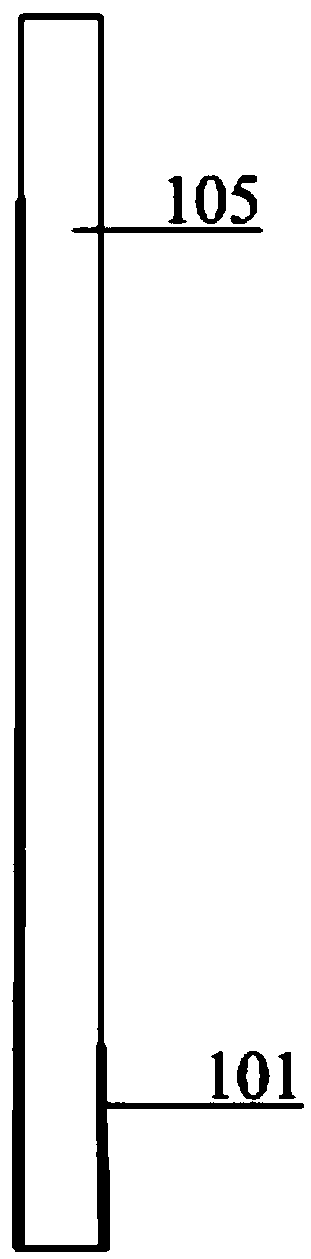
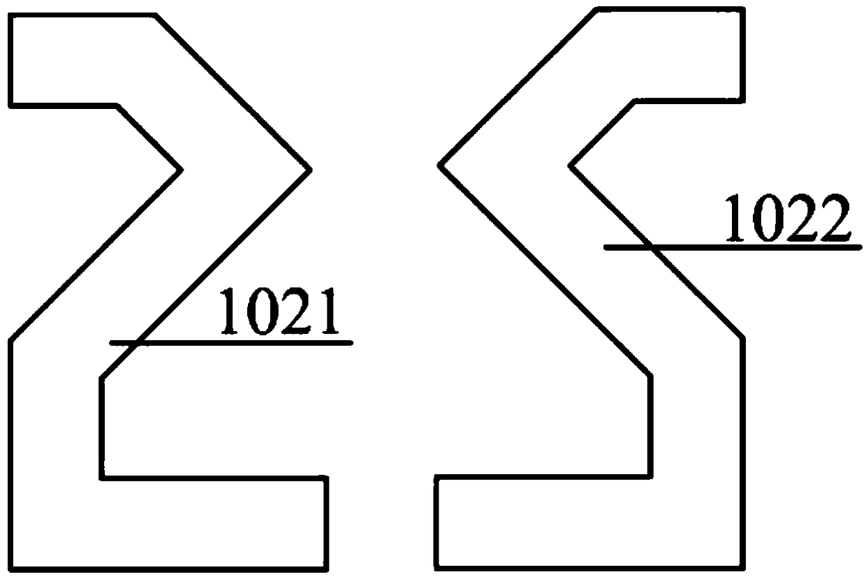
[0020] The purpose of the present invention is achieved in this way: comprising a dielectric substrate 105, a microstrip transmission line 103 arranged on the dielectric substrate, a first dipole radiation unit 102, a second V-shaped parasitic radiation unit 104, and a Part of the ground plane 101 . The first dipole radiating unit 102 is composed of two arms bent into an S shape 1021 and an inverted S shape 1022. The first dipole radiating unit 102 is directly connected to the microstrip transmission line 103 for feeding, and the second V-shaped parasitic radiating unit 104 is coupled and fed through the gap with the first dipole radiating unit 102 . The microstrip transmission line 103 is connected to the inner conductor of the connector, and the outer conductor of the connector is connected to part of the ground plane 101 . The present invention also includes such structural features:

[0021] The antenna adopts a combination of microstrip transmission line direct feeding ...

Embodiment 2

[0027] combine Figure 1 to Figure 4 , the present invention designs a low-profile broadband antenna. The designed antenna adopts the combination of microstrip transmission line direct feeding and parasitic coupling indirect feeding, and the integrated design of the combination of double radiation elements, so as to realize the longitudinal and lateral direction of the antenna. Low-profile design, at the same time, the structural size of the antenna can be adjusted to achieve broadband design.

[0028]The antenna involved in the present invention mainly includes a dielectric substrate 105, a microstrip transmission line 103 disposed on the dielectric substrate, a first dipole radiation unit 102, a second V-shaped parasitic radiation unit 104, and a part of the ground connection disposed on the back of the dielectric substrate. Ground 101. The first dipole radiating unit 102 is composed of two arms bent into an S shape 1021 and an inverted S shape 1022. The first dipole radiat...


PUM


Abstract

The invention discloses a low profile broadband antenna and relates to the field of the antenna structure. The low profile broadband antenna comprises a dielectric substrate (105), a microstrip transmission line (103) arranged on the dielectric substrate, a first dipole radiation unit (102), a second V-shaped parasitic radiation unit (104) and a partial ground plane (101) arranged at a back surface of the dielectric substrate, wherein the first dipole radiation unit (102) is composed of S-shaped (1021) and inverted-S-shaped (1022) structures of which two arms are bent, the first dipole radiation unit (102) is directly connected with the microstrip transmission line (103) for feeding, the second V-shaped parasitic radiation unit (104) is coupled with a gap with the first dipole radiation unit (102) for feeding, the microstrip transmission line (103) is connected with an inner conductor of a connector, and an outer conductor of the connector is connected with the partial ground plane (101). The low profile broadband antenna has characteristics of low profile, small size and easy integration, can be mixed with reactive components and has broad application prospects.

Description

technical field [0001] The invention relates to the field of antenna structures, in particular to a low-profile broadband antenna. Background technique [0002] With the rapid development of electronic science and technology, wireless communication technology and its derivatives have become more and more popular, electronic equipment has more functions, and the required signal bandwidth is also increasing. Antennas that are essential for wireless communication Put forward higher requirements and strict parameters. And in the current wireless communication technology, people pay more and more attention to information security. In order to ensure the security of communication, there are many measures that are most commonly used at present, such as multi-band, multi-antenna and broadband frequency hopping technology. In the broadband frequency hopping technology, as the frequency hopping rate becomes higher and higher, the frequency range of the frequency hopping becomes wider...

Claims


Application Information

Patent Timeline
Patent Type & Authority Applications(China)
IPC IPC(8): H01Q1/38H01Q1/48H01Q1/50H01Q9/28
CPCH01Q1/38H01Q1/48H01Q1/50H01Q9/285
Inventor 李迎松董玥
Owner HARBIN ENG UNIV
Why Eureka
Try Eureka