

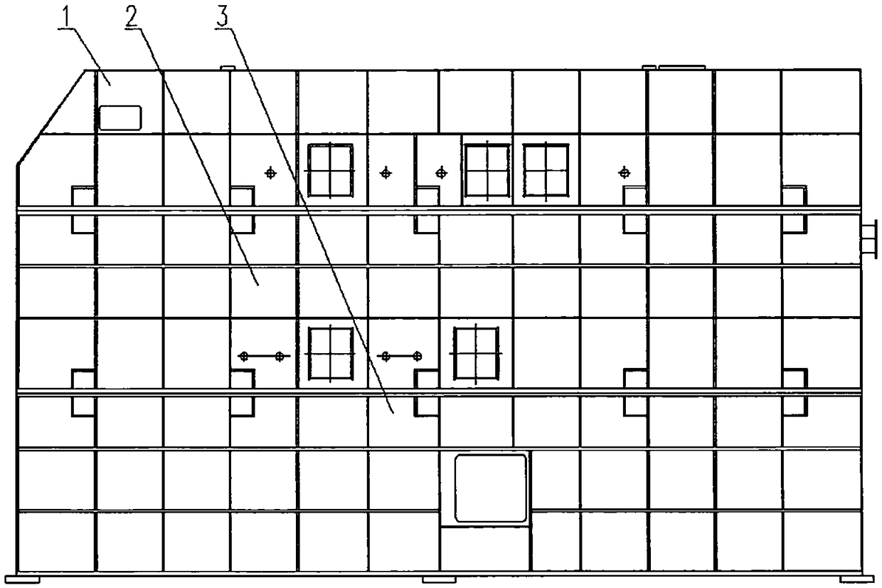
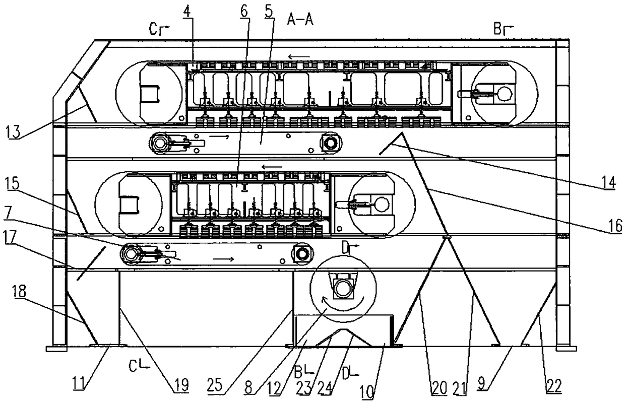
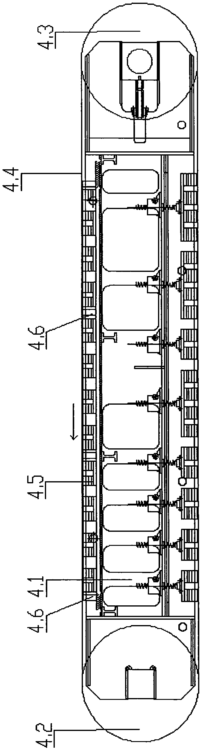
Multi-stage dry magnetic separator
A dry magnetic separation and magnetic separator technology, applied in conveyors, magnetic separation, high gradient magnetic separators, etc., can solve the problems of low magnetic separation efficiency, reduced production efficiency, easy damage to roller bearings and stuck, etc. Achieve super wear resistance, improve service life, and ensure the effect of normal production
- Summary
- Abstract
- Description
- Claims
- Application Information
AI Technical Summary
Problems solved by technology
Method used
Image

Examples
Embodiment 1
[0107] After being crushed and pre-selected by a mobile dry separation station, the boundary ore produced during the mining process of an iron mine in Ma’anshan has a particle size of less than 60 mm. The subsequent selection costs are high, or even a loss, and the use value is not high. If the multi-stage dry magnetic separator and high-pressure roller mill are used to crush to a particle size of less than 8 mm, the pre-selection effect is very obvious:
[0108] category
[0109] The magnetic field strength of the upper layer of the primary magnetic separation main conveyor 4 is 3000 gauss, and the magnetic field strength of the lower layer is 4500 gauss. The magnetic field strength of the upper layer of the secondary magnetic separation main conveyor 6 is 3000 gauss, and the magnetic field strength of the lower layer is 4700 gauss. 167m / min, secondary conveyor belt 6.4 speed 100-167m / min, primary auxiliary conveyor belt 5.4 speed 100-170m / min, secondary auxiliary co...
Embodiment 2
[0111] The dry-separated tailing waste rock of an iron mine in Ma'anshan was crushed to a particle size of less than 8 mm, and then pre-selected by a multi-stage dry magnetic separator. The parameters are as follows:
[0112] category
[0113] The magnetic field strength of the upper layer of the primary magnetic separation main conveyor 4 is 3000 Gauss, and the magnetic field strength of the lower layer is 4700 Gauss. The magnetic field strength of the upper layer of the secondary magnetic separation main conveyor 6 is 3000 Gauss, and the magnetic field strength of the lower layer is 4800 Gauss. 167m / min, secondary conveyor belt 6.4 speed 100-167m / min, primary auxiliary conveyor belt 5.4 speed 100-170m / min, secondary auxiliary conveyor belt 7.4 speed 100-170m / min, primary magnetic separation left drum magnetic field strength 5000 Gauss, the magnetic field strength of the left drum of the secondary magnetic separation is 5000 Gauss, and the magnetic field strength of ...
Embodiment 3
[0115] The grade of an iron mine in Dai County, Shanxi Province is relatively high. In order to obtain higher economic and technical indicators, the ore was crushed with a high-pressure roller mill to a particle size of less than 20 mm. After pre-selection by a multi-stage dry magnetic separator, the effect is remarkable. as follows:
[0116] category
[0117] The magnetic field strength of the upper layer of the primary magnetic separation main conveyor 4 is 3000 Gauss, and the magnetic field strength of the lower layer is 4000 Gauss. The magnetic field strength of the upper layer of the secondary magnetic separation main conveyor 6 is 3000 Gauss, and the magnetic field strength of the lower layer is 4500 Gauss. 167m / min, secondary conveyor belt 6.4 speed 100-167m / min, primary auxiliary conveyor belt 5.4 speed 100-170m / min, secondary auxiliary conveyor belt 7.4 speed 100-170m / min, primary magnetic separation left drum magnetic field strength 5000 Gauss, the magnetic...
PUM
 Abstract
Description
Claims
Application Information