Numerical control dispensing equipment and dispensing method

A dispensing and equipment technology, which is applied in the direction of coating, liquid coating device on the surface, etc., can solve the problems of low production efficiency, heavy repetitive labor, etc., achieve fast glue application, reduce labor load, and improve work efficiency Effect

Inactive Publication Date: 2018-11-13
BEIJING GOLDWIND SCI & CREATION WINDPOWER EQUIP CO LTD
View PDF7 Cites 5 Cited by
  • Summary
  • Abstract
  • Description
  • Claims
  • Application Information

AI Technical Summary

Problems solved by technology

[0004] This application provides a numerical control dispensing equipment and a dispensing method to solve the problems of large amount of repetitive labor and low production efficiency in the prior art

Method used


Image

  • Numerical control dispensing equipment and dispensing method
  • Numerical control dispensing equipment and dispensing method
  • Numerical control dispensing equipment and dispensing method

Examples


Embodiment 1

[0089] Embodiment 1 of the present application provides the first dispensing extension method, and the schematic flow chart of the method is as follows Figure 13 shown, including the following steps:

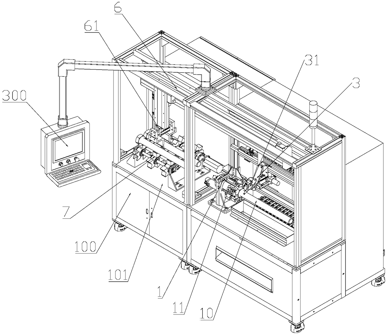
[0090] S101 : Control the workpiece clamping part 11 to clamp the first end of the workpiece 10 .

[0091] Optionally, in the embodiment of the present application, before S101, the numerical control dispensing equipment may also reset each component according to the dispensing mode information of the workpiece 10 .

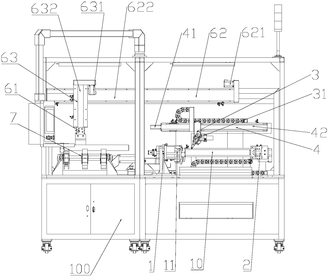
[0092] S102: Control the first slide rail driving part 41 to drive the pushing mechanism 2 to move along the first slide rail 42, so that the pushing mechanism 2 is close to the second end of the workpiece 10.

[0093] S103 : Control the tightening drive part 24 to drive the tightening slider 23 to move along the tightening base 22 , so that the tightening part 21 abuts against the second end of the workpiece 10 .

[0094] S104: Control the workpiece clamping pa...

Embodiment 2

[0099] Embodiment 2 of the present application provides the second dispensing extension method, the schematic flow chart of the method is as follows Figure 14 shown, including the following steps:

[0100] S201 : Control the manipulator 200 to transport the workpiece 10 to the conveyor belt 71 .

[0101] S202: Control the conveyor belt 71 to transfer the workpiece 10 to the first workpiece position.

[0102] S203: Control the workpiece grasping part 61 to grab the workpiece 10 at the first workpiece position, and transport the workpiece 10 to the second workpiece position for clamping by the workpiece clamping part 11 .

[0103] Specifically, in S203, the sliding table 633 is driven to move by controlling the third sliding rail driving part 621, so that the fourth sliding rail mechanism 63 can move along with the sliding table 633 along the third sliding rail 622, and the fourth sliding rail driving part 631 drives the workpiece grasping part 61 to move along the fourth sli...


PUM


Abstract

The embodiment of the invention provides numerical control dispensing equipment and a dispensing method. The numerical control dispensing equipment comprises a spindle mechanism (1), a push-tighteningmechanism (2) and a dispensing mechanism (3). The spindle mechanism (1) and the push-tightening mechanism (2) are oppositely arranged along the first specified axis. The spindle mechanism (1) comprises a workpiece clamping part (11) capable of rotating around the first specified axis and used for clamping the first end of a workpiece (10). The push-tightening mechanism (2) comprises a push-tightening part (21) capable of rotating around the first specified axis and used for abutting against the second end of the workpiece (10). The dispensing mechanism (3) comprises a dispensing gun (31) capable of moving at the first preset position and / or the second preset position in the direction parallel to the first specified axis. According to the numerical control dispensing equipment, the gluingprocess of the workpiece can be automatically completed, and the labor intensity of workers is relieved; and compared with a manual gluing mode, the gluing speed is higher, long-time uninterrupted working can be achieved, and thus the work efficiency is greatly improved.

Description

technical field [0001] The present application relates to the technical field of bolt lubricating equipment, in particular to a numerical control dispensing equipment and a dispensing method. Background technique [0002] Bolt connection is an important connection method, which is widely used because of its convenient operation and reliable connection. For example, in wind turbines, bolt connections are mainly used between components. Before the bolt is used, it is generally necessary to brush the solid lubricating paste on the threaded part and the end of the bolt head to obtain a more stable torque coefficient, improve the quality of the bolt pre-tightening, and prevent dry friction between the threads and cause seizure. [0003] According to a prior art known by the inventor, the solid lubricating paste is brushed on the end of the bolt head mainly manually. However, this method involves a large amount of repetitive labor and low production efficiency. Contents of the ...

Claims


Application Information

Patent Timeline
Patent Type & Authority Applications(China)
IPC IPC(8): B05C5/02B05C13/02B05C11/00
CPCB05C5/0212B05C11/00B05C13/02
Inventor 石友方志强庄建新
Owner BEIJING GOLDWIND SCI & CREATION WINDPOWER EQUIP CO LTD
Why Eureka
Try Eureka