
Tool setting device for milling key groove

A tool setting device and keyway technology, applied in feeding devices, automatic control devices, milling machine equipment, etc., can solve the problems of poor control of tool setting accuracy, cumbersome operation process, affecting production efficiency, etc., and achieve easy popularization and use, tool setting The effect of easy operation and simple structure

Active Publication Date: 2018-11-13
HUAIYIN INSTITUTE OF TECHNOLOGY
View PDF10 Cites 2 Cited by
  • Summary
  • Abstract
  • Description
  • Claims
  • Application Information

AI Technical Summary

Problems solved by technology

[0003] For example, the Chinese patent with the publication number CN202845904A and the Chinese patent with the publication number CN201109048Y respectively disclose a tool setting device for milling cutters. Therefore, it is necessary to adjust the tool setting device to the corresponding position accurately to ensure the complete fit between the workpiece and the tool setting device, and the tool setting can only be performed after the tool setting device is attached to the workpiece, so the operation of the tool setting The process is cumbersome and requires multiple up and down movements and rotations of the tool setting device, as well as horizontal adjustment of the workpiece by moving the workpiece clamping platform. Due to line of sight errors, the fit between the workpiece and the tool setting device can only be roughly guaranteed To a certain extent, the accuracy of tool setting is not easy to control, and the tool setting time is longer, which affects the production efficiency; moreover, the above tool setting device is directly connected with the fixture of the milling cutter. After the tool setting is completed, the milling cutter needs to be installed. Not only the operation It is cumbersome, and the reinstallation of the milling cutter will cause installation errors with the previous tool setting device, resulting in inaccurate tool setting and poor tool setting effect

Method used


Image

  • Tool setting device for milling key groove
  • Tool setting device for milling key groove
  • Tool setting device for milling key groove

Examples


Embodiment Construction

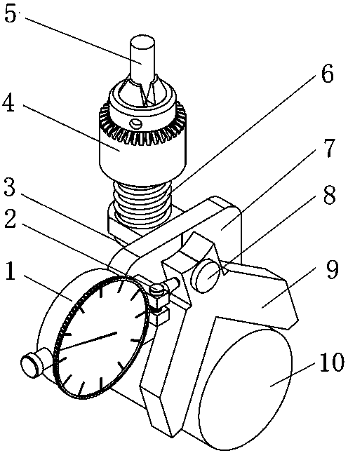
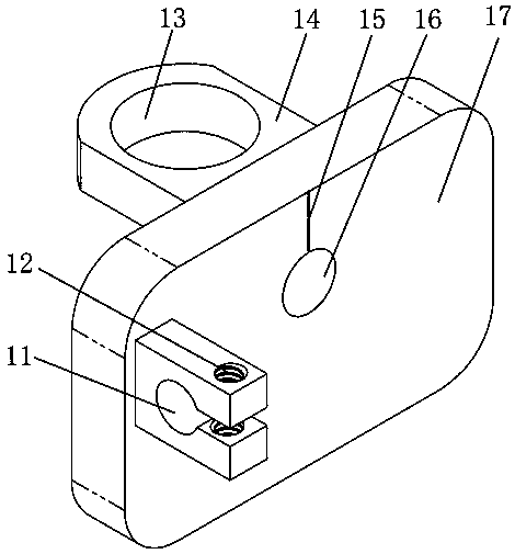
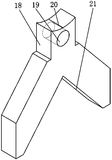
[0029] combine Figure 1~Figure 6 It can be seen that a tool setting device for milling a keyway of the present invention includes a vertical plate 7 fixed below the milling cutter 5 of the milling machine, one side end surface of the vertical plate 7 is oscillatingly connected with a pendulum plate 9, and the pendulum plate 9 The bottom is provided with a "V"-shaped groove 21, and the top of the swing plate 9 is connected to the vertical plate 7 through a swing shaft 8. The axis of the swing shaft 8 is located at the bisector of the included angle of the "V"-shaped groove 21. On the straight line, the vertical plate 7 is provided with a reference line structure 15, and the top of the pendulum plate 9 is provided with a knife setting line structure 20 corresponding to the reference line structure 15, and the reference line structure 15 is located in a "V"-shaped groove 21 On the straight line where the bisector of the included angle is located, the tool alignment structure 20 ...


PUM


Abstract

The invention discloses a tool setting device for milling a key groove. The tool setting device comprises a vertical plate fixed below a milling cutter of a milling machine; the end face of one side of the vertical plate is in swinging connection with a pendulum plate, a V-shaped groove is formed in the bottom of the pendulum plate, the top of the pendulum plate is in swinging connection with thevertical plate through a swinging shaft, and the axis of the swinging shaft is located on the straight line where the angle bisector of the V-shaped groove is located at; and a baseline structure is arranged on the vertical plate, a tool setting line structure corresponding to the baseline structure is arranged at the top of the pendulum plate, the baseline structure is located on the straight line where the angle bisector of the V-shaped groove is located at, and the tool setting line structure is located in a plane composed by the axis of the swinging shaft and the angle bisector of the V-shaped groove. The tool setting device for milling the key groove is simple in structure, convenient to operate in tool setting, and high in tool setting precision, and improves the production efficiency, and is also easy to use and popularize.

Description

technical field [0001] The invention relates to the technical field of milling tool setting, in particular to a tool setting device for milling key grooves. Background technique [0002] The key connection is to realize the circumferential fixation between the shaft and the parts on the shaft (such as gears, pulleys, etc.), and to transmit motion and torque. Due to its reliable operation and standardized keys, it has been widely used. The keyway is often processed by milling. Due to the high symmetry requirements of the keyway, tool setting is very important during milling. The existing technology has low precision of tool setting, cumbersome operation, low production efficiency, and cannot guarantee the symmetry requirement of the keyway. Especially for workpieces with arc-shaped processing surfaces, such as cylindrical workpieces, fan-shaped interface workpieces, etc. [0003] For example, the Chinese patent with the publication number CN202845904A and the Chinese patent...

Claims


Application Information

Patent Timeline
Patent Type & Authority Applications(China)
IPC IPC(8): B23Q15/22B23C3/30
CPCB23C3/30B23Q15/22
Inventor 方晓堂周蓉颜光稳姜海林赵纯
Owner HUAIYIN INSTITUTE OF TECHNOLOGY
Learn More